


22
4200FA Installation and Operation Manual
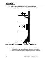
4.1.4
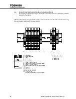
Power Connection Cable Routing and Conduit Placement 15/25/30 kVA
The following illustrates the proper cable routing that should be followed during the power
connection process of the 15/25/30 kVA.
Note:
1) Input and Output conductors shall be installed in separate conduits, and installed in
accordance with the latest edition of NEC and the Local Authority having jurisdiction.
2) Battery conductors shall be installed in a separate conduit and be of low resistance type.
CONDUIT MOUNTING PANEL
INPUT CONDUIT
OUTPUT CONDUIT
BATTERY CONDUIT
Summary of Contents for 4200FA CT
Page 2: ...4200FA Installation and Operation Manual ...
Page 4: ...4200FA Installation and Operation Manual ...
Page 10: ...iv 4200FA Installation and Operation Manual This Page Intentionally Left Blank ...
Page 14: ...4 4200FA Installation and Operation Manual NOTE This Label for Battery Units Only ...
Page 85: ...4200FA Installation and Operation Manual 75 APPENDIX A Seismic Anchorages ...
Page 86: ...76 4200FA Installation and Operation Manual ...
Page 87: ...4200FA Installation and Operation Manual 77 ...
Page 88: ...78 4200FA Installation and Operation Manual ...
Page 96: ......
Page 97: ......


