G005857
1
2
3
4
5
4
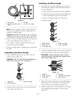
Figure 44
1.
Pressure filter assembly
4.
Washer (5/16 inch)
2.
Pressure filter mount
5.
Flange nut (5/16 inch)
3.
Bolt (5/16 x 1 inch)
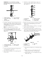
3. Mount the pressure filter and mount assembly to
the right boom upright frame on the machine at the
location as shown Figure 45. Use two bolts (5/16 x
1 inch), two washers (5/16 inch) and two flange nuts
(5/16 inch) to secure the assembly to the frame.
G005873
1
2
3
4
5
6
Figure 45
1.
Pressure filter and mount
assembly
4.
Bolt (5/16 x 1 inch)
2.
Right boom frame
5.
Washer (5/16 inch)
3.
Valve manifold
6.
Lock nut (5/16 inch)
20
Installing the Tank Drain
Parts needed for this procedure:
1
Tank drain assembly
4
Lock washer
4
Lock nut
1
Template
1
90 degree elbow fitting
Procedure
1. Remove the tank drain hose. Loosen the clamp
securing the hose to the existing elbow fitting and
slide the clamp up the hose toward the tank drain
ball valve assembly.
2. Remove the drain hose from the existing elbow
fitting.
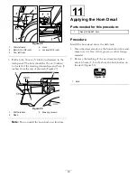
3. Loosen the retaining nut on the existing elbow fitting
and remove it from the tank drain outlet (Figure 46).
Discard the fitting.
1
2
3
4
5
G005874
1
2
3
4
5
Figure 46
1.
Sump, main tank
4.
Plastic ring nut
2.
Outlet drain
5.
Retaining nut, existing
elbow fitting
3.
Seal
21


