background image

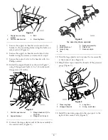
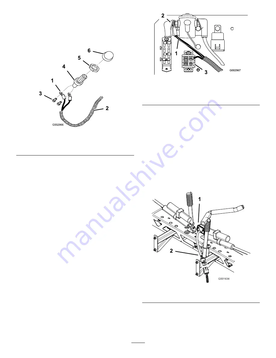
2. Remove the horn button cap and thread the retaining

ring onto the exposed threads of the switch.

3. Connect the white and yellow wires at the end of the

wire harness to the back of the horn switch using the
two screws included (Figure 37).

Figure 37

1.

White and red wires

4.

Horn switch

2.

Wire harness

5.

Retaining ring

3.

Screws

6.

Horn button

4. Move the switch assembly under the dash and push

it through the hole drilled in the dash previously.

5. Screw the horn button cap onto the switch threads

to secure the assembly to the dash.

Note:

Adjust the retaining ring and horn button

cap as necessary.

Installing the Wire Harness for Horn
and Brake

1. Run the wire harness from the horn button, under

the dash panel, through the wire access hole in the
floorboard, and through the frame hooks along side
of the headlight wire harness to the electrical panel
located under the operator’s seat.

2. Under the floorboard, connect the wire harness to

the new brake switch. Secure the harness to the
switch using a plastic wire tie.

3. Under the floor board, connect the two quick

connect terminals on the black and white wires to
the horn.

4. Under the operator’s seat, connect the single black

wire (ground) in the middle of the wire harness to
the ground block (Figure 38) located under the seat
near to the solenoid.

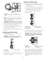
Note:

Right and left sides are determined from the

normal operating position.

Figure 38

1.

Red power wire from the
wire harness.

3.

Black wire to ground block

2.

Solenoid, hot or input side

5. Connect the red power wire to the right side of the

solenoid (Figure 38), located under the seat.

Note:

Connecting the wire harness to the hot or

input side solenoid post will allow the horn to be
active when the ignition key is in the Off position.

Note:

The hot or input side has constant 12V

power.

6. Run the wire harness end with the tail light connector

along the left side of the frame toward the rear of
the machine.

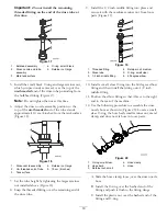
7. Connect the tail light connector on the wire harness

to the tail light (Figure 39).

Figure 39

1.

Tail light

2.

Pigtail connector

8. Tie the wire harness down to the frame along with

the existing wiring.

Note:

Make sure the harness does not touch any

part of the engine exhaust system.

18

Summary of Contents for 41339

Page 1: ...ollow have steps that rework installations performed in preceding steps Disregard any installation instructions found in those individual kits Loose parts not packaged within individual kits are denot...

Page 2: ...e nozzle hose 1 Retainer fork small 3 Retainer fork large 1 8 Plastic tie 3 Install the hoses Rinse Kit Flange bolt 5 16 x 3 4 inch 2 9 Flange nut 5 16 inch 2 Install the battery cover fasteners CE Ki...

Page 3: ...g 1 Install the tank drain BBA Kit Mixing tee 1 Retainer forks small 3 Bypass hose 1 21 1 Install the bypass line BBA Kit Filter supply hose 1 22 Manifold supply hose 1 Install the pressure filter hos...

Page 4: ...llow all manufacturer recommendations and precautions Keep chemicals away from your skin Should contact occur wash the affected area thoroughly with soap and clean water Wear goggles and any other pro...

Page 5: ...move the four screws securing the supply tee to the mounting bracket Figure 4 Remove the supply tee and hoses 2 2 1 G005781 Figure 4 1 Supply tee mounting bracket 2 Screws 3 Install the new control va...

Page 6: ...05784 4 1 4 2 3 Figure 7 1 Control valve bracket 3 Flange head bolt 1 4 x 3 4 inch 2 Support bracket 4 Flange nut 1 4 inch 11 Connect the large adapter end of the tee assembly to the control valve Fig...

Page 7: ...spray gun in the gun bracket 5 Installing the Rinse Tank Bulkhead Fitting Parts needed for this procedure 1 Bulkhead 1 Plastic ring nut Procedure 1 Remove the fastener securing the right side of the...

Page 8: ...that the retainer fork will come from the front to the back of the machine Figure 12 9 Install the rinse tank cap 10 Install the rinse tank assembly with the new fitting to the machine 11 Secure the t...

Page 9: ...be Figure 14 Installing the Rinse Nozzle 1 Locate the rinse nozzle bulkhead in loose parts If the bulkhead is shipped assembled disassemble as shown in Figure 15 A Remove the plastic ring nut from the...

Page 10: ...ed fitting over the remaining end of the rinse tube 9 Install the 1 2 inch middle fitting into place and secure it with the medium retainer nut from loose parts Figure 19 G005796 1 2 3 4 5 6 Figure 19...

Page 11: ...e main tank to the upper mixer tee Discard this hose and retain the forks for later use 4 Brush a non petroleum based lubricate such as vegetable oil on the bulkhead fitting reducer and O ring Figure...

Page 12: ...1 Rinse tank valve blue 5 Boom supply hose existing 2 Rinse nozzle valve green 6 Retainer fork large 3 Control valve spray gun 7 Retainer fork large existing 4 Rinse nozzle hose 6 Remove the retainer...

Page 13: ...7 Rinse nozzle hose 11 Retainer fork small 4 Rinse tank suction hose 8 Rinse tank valve 12 Retainer fork large Installing the Suction Hose 1 Locate suction hose in loose parts 2 Install the hose from...

Page 14: ...e Figure 26 4 Secure the rinse nozzle hose to the 60 degree elbow fitting by threading the small retainer nut over the elbow fitting Make sure the small clear O ring is seated in the small retainer nu...

Page 15: ...1 2 3 Figure 29 1 Drill hole here 3 Steering column 2 Dash Note Do not install the horn button at this time 11 Applying the Horn Decal Parts needed for this procedure 1 Decal 104 6957 horn Procedure I...

Page 16: ...letely Repeat the process for the bottom part of the decal just below the dial Important Do not attempt to remove the dial to facilitate the installation of the decals Removing the dial will damage to...

Page 17: ...1 Measure from the end of the booms as shown in Figure 35 Figure 35 1 Decal 3 Measure 90 cm 35 1 2 inches 2 Boom 2 Clean the decal area and make sure the area is free of dirt grease or other foreign m...

Page 18: ...sing a plastic wire tie 3 Under the floor board connect the two quick connect terminals on the black and white wires to the horn 4 Under the operator s seat connect the single black wire ground in the...

Page 19: ...tch 3 Brake released 2 Brake engaged Note If the brake light stays on when the pedal released loosen the bolts securing the brake switch and adjust position of the switch so the light extinguishes whe...

Page 20: ...reducer in loose parts Locate the filter flush hose in loose parts refer to Figure 1 2 Install the spring ball and red plug then elbow on hose assembly into the vertical pressure inlet on the bottom o...

Page 21: ...asher 5 16 inch 3 Valve manifold 6 Lock nut 5 16 inch 20 Installing the Tank Drain Parts needed for this procedure 1 Tank drain assembly 4 Lock washer 4 Lock nut 1 Template 1 90 degree elbow fitting P...

Page 22: ...and the external lower section 8 Drop the new drain base into the tank and move it into position over the drain hole and new drilled holes Figure 48 G005876 1 2 3 4 5 6 Figure 48 1 Drain base 4 Cover...

Page 23: ...of the machine for both front and back tank straps This will allow the tank to be raised slightly to accommodate the removal and installation of components 2 Locate the valve manifold at the back of t...

Page 24: ...tion in loose parts Remove the retainer forks 6 Locate the filter flush hose coming from the bottom of the pressure filter assembly installed previously Install the open 90 degree fitting from this ho...

Page 25: ...e tank above the frame The hose should lay over the right rear fender point toward the rear of the machine Lower the tank and make sure the hose is not being pinched 11 Install the end of the hose wit...

Page 26: ...ally orientated rinse valve on the control valve assembly Install the 90 degree fitting to the open port on the rinse valve and use the existing large fork to secure the connection Figure 56 6 Locate...

Page 27: ...the pressure tap was removed previously Figure 57 4 Install the metal tee fitting to the exposed end of the brass straight fitting Use the center port on the metal tee fitting Figure 57 Install the wr...

Page 28: ...s and connections for leaks A Fill the main tank with 50 gallons of clean water B Spray approximately 30 gallons through the boom system refer to the Multi Pro 1250 Operator s Manual Check hose connec...

Page 29: ...Notes 29...

Page 30: ......

Page 31: ......

Page 32: ......

Reviews: