


Note:
If the engine does not start the switch is
adjusted properly. If the engine starts, the position
of the neutral switch is incorrect and you need to
adjust it again before continuing with the rest of
the installation instructions for this kit; refer to
steps
, and
.
15
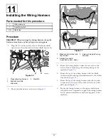
Installing the Seat Shroud
and ROP Shield (HD and HDX
series models), and Coolant
Tank (non-HD models)
No Parts Required
Installing the Seat Shroud
1.
Align the opening in the seat shroud for the parking
brake with the parking brake handle (
and
2.
For Workman models with an manual transmission,
align the hole in the gear selector boot with the rod
for the gear selector.
3.
Align the opening in the seat shroud for the rods for
the lift bed control, high-low range shifter, and the
differential lock (
and
).
4.
Lower the seat shroud down (
5.
Align the holes in the shroud for the seat mounting
with the seat support brackets of the chassis.
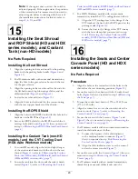
Installing the ROPS Shield
1.
Align the holes in the ROPS shield with the hole in the
brackets on the ROPS bar (
).
2.
Secure the ROPS shield to the ROPS bar with the 6
carriage bolts and 6 nuts (
) that you removed
in step
of
Removing the ROPS Panel and Seat Shroud
(page 8)
.
Installing the Coolant Tank (non-HD
models,) and the CVT Cooling Duct
(HDX-Auto Workman models)
1.
For non-HD models, align the left and right flanges
of the coolant-tank bracket with the slots in the seat
shroud (
); refer to
Tank (non-HD models), ROPS Shield, and Seat Shroud
(HD and HDX series models) (page 7)
.
2.
Lower the tank into the slots until the tank is firmly
seated (
); refer to
Tank (non-HD models), ROPS Shield, and Seat Shroud
(HD and HDX series models) (page 7)
.
3.
For HDX Workman models with an automatic
transmission, install the CVT cooling duct as follows:
A.
Align the CVT cooling duct to the flange of the
CVT intake at the back of the ROPS panel on the
passenger side (
).
B.
Secure the duct to the flange of the CVT intake
with the hose clamp that you removed in step
of
4 Removing the Coolant Tank (non-HD
models), ROPS Shield, and Seat Shroud (HD and
HDX series models) (page 7)
.
16
Installing the Seats and Center
Console Panel (HD and HDX
series models)
No Parts Required
Procedure
1.
Align the holes in the seat rails with the holes in the
shroud for the seat mounting positions (
).
2.
Secure the seats to the chassis with the 8 socket-head
bolts (
) that you removed in step
of
.
3.
Torque the socket head bolts to 1978 to 2542 N-cm
(175 to 225 in-lb).
4.
Align the control cover over the control rods at the
center console (
); refer to
Center-Console Covers (page 5)
.
5.
Secure the cover with the 6 screws (
and
) that you removed in step
of
Center-Console Covers (page 5)
.
6.
For Workman models with an automatic transmission
install the shift indicator as follow:
A.
Connect the harness of the shift indicator
to the machine-harness connector (
)
that you separated in step
of
Center-Console Covers (page 5)
.
B.
Align the shift-indicator cover over the control
rod at the center console (
).
7.
Secure the cover with the 4 screws (
) that you
removed in step
of
.
8.
For Workman models with an manual transmission,
thread the jam nut and shifter knob onto the
20


