


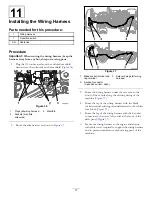
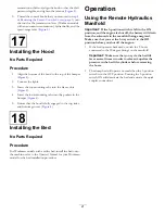

Figure 6
1.
Brake lever
5.
Transmission lever (L
position)
2.
Knob (hydraulic-lift lever)
6.
Hydraulic-lift lock (locked
position—left)
3.
Knob (speed-range lever)
7.
Speed-range lever (A
position)
4.
Knob ( transmission lever)
3.
Move the hydraulic-lift lever to the raise the bed
position, and set the hydraulic-lift lock (
and
4.
Remove the remaining knobs from console levers by
rotating the knobs counterclockwise (
).
5.
For Workman models with an automatic transmission
remove the shift indicator as follow:
A.
Remove the 4 hex-head screws that secure the
shift-indicator cover to the seat shroud (
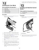
Figure 7
Workman models with an Automatic Transmission
1.
Indicator connector
4.
Control cover
2.
Shift-indicator cover
5.
Machine-harness
connector
3.
Hex-head screws
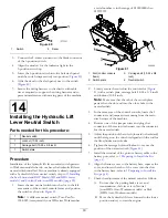
B.
Lift shift indicator assembly up, disconnect
electrical connectors of the machine harness and
indicator, and remove the indicator from the
machine. (
).
6.
Remove the 6 hex-head screws that secure the control
cover to the seat shroud, and remove the control cover
(
and
Figure 8
Workman models with a Manual Transmission
1.
Screw
2.
Cover plate
6


