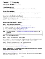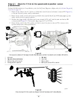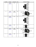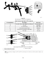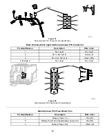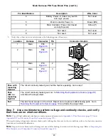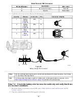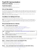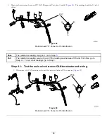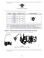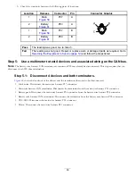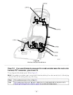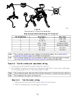
Main Harness P03 Fuse Block Pins (cont'd.)
Pin Identification
Description
Wire Color
4
Battery Power In (fused key switch
and logic power)
Not used
5
Main Contactor Power In
Brown (BN)
6
Main Contactor Power Out (fused
work-light power)
Yellow (Y)
7
Not used
Not used
8
Not used
Not used
3.
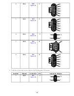
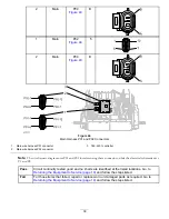
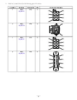
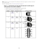
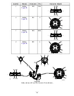
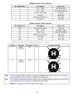
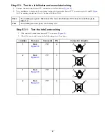
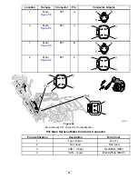
Verify that a short does not exist between the following pairs of locations:
Location
Harness
Connector
Pin
Connector Graphic
1
Main
P04
A
2
Main
P04
B
B
A
1
Main
P19
2
2
Main
P19
3
3
2
1
8
6
5
4
7
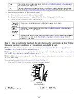
Pass with
repeating
fault 04:
The circuit continuity tested good, but the fault is repeating. Go to step 7.
Pass
with no
repeating
fault 04:
The circuit continuity tested good. Go to
Returning the Equipment to Service (page 19)
and follow the steps listed.
Fail
The test found an open in the circuit. Repair and or replace malfunctioning parts. Go to
Returning the Equipment to Service (page 19)
and follow the steps listed.
Step 7:
Use a multimeter to perform voltage and continuity checks, and verify
that there are no short conditions.
Note:
You will find additional wire harness and connector information in
Appendix A: Wire Harnesses (page 113)
and
Appendix B: Toro Electronic Controller Connections (page 135)
When performing voltage and continuity checks, and verifying that there are no short conditions, refer to for harness connector
locations and terminal identification.
Note:
Inspect the wire harnesses for damage and wear while checking the items in the following steps. Refer to
Wire Harnesses and Component Connector Assemblies (page 13)
.
49

