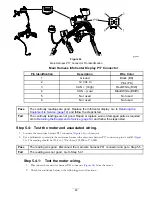
3.
Rotate the key switch to the S
TART
position and hold it until the InfoCenter LCD display lights up, then release the
key switch to the R
UN
position. Check for a stable reading of 42 to 64 Vdc on the multimeter (that was connected in
the previous step).
Note:
An initial voltage reading that slowly decreases most likely indicates a possible open condition in the coil circuit.
4.
Rotate the key switch to the O
FF
position, and then disconnect the multimeter.
Pass
The voltage reading was good. Go to
Returning the Equipment to Service (page 19)
and follow
the steps listed.
Fail
The voltage reading was not good. (Could be a wrong reading or a reading that gradually
decreases.) Go to step 5.
Step 5:
Check the wire harness for continuity, and test the resistance of the
main contactor coil.
Disconnect the battery pack. Refer to
Disconnecting the Battery Pack (page 17)
.
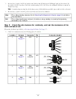
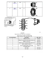
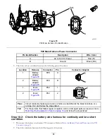
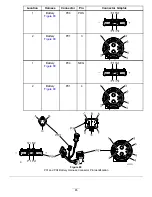
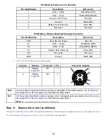
1.
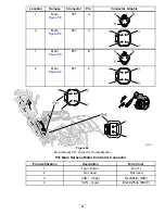
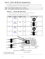
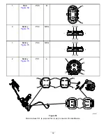
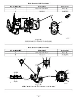
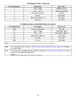
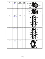
Check for continuity between the following pairs of locations.
Location
Harness
Connector
Pin
Connector Graphic
1
Main
P13
E
A
B
C
D
E
F
2
Main
Main
contactor
J03
J02, J05
J03
J01
J04
1
Main
Main
contactor
J04
J02, J05
J03
J01
J04
2
Main
P02
1
1
12
7
6
77

