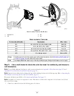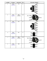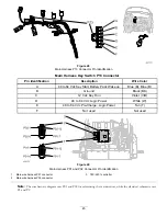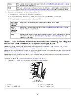
Fault 05 Communication
InfoCenter Display:
Communication Fault
Fault Description
The TEC-2401 is not receiving CAN-bus data from the motor.
Circuit Description
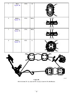
The twisted-pair CAN-bus system establishes data pathways between the machine components. The signal names for these 2
wires are CAN + (high) and CAN – (low). The CAN bus circuit provides the TEC-2401 controller with communication to
the battery pack controller, motor controller, and InfoCenter user interface display. The twisted-pair CAN bus for the eFlex
has 2 terminators (120 ohms each)..
Note:
Communication depends on the CAN bus, not on the InfoCenter. While the machine can function without an
InfoCenter, do not operate the machine in this condition.
Conditions for Setting the Fault
The TEC-2401 has not received CAN-bus data for more than 2.5 seconds.
Note:
If the CAN is down between the InfoCenter and the TEC, the InfoCenter does not receive the fault message to
display. If the CAN failure is between the battery pack and TEC, the battery pack shuts down. The only CAN failure that
results in a fault on the display is with the motor. The other CAN failures appear in the fault log as an historical event,
viewable via Toro DIAG.
Recommended Service Actions
Step 1:
Verify that the fault repeats.
1.
Clear the InfoCenter fault log. Refer to
Clearing the InfoCenter Fault Log (page 19)
.
2.
Disconnect the battery pack for 30 seconds. Refer to
Disconnecting the Battery Pack (page 17)
.
3.
Connect the battery pack. Refer to
Connecting the Battery Pack (page 17)
.
4.
Start and operate the machine. Refer to the
eFlex Operator’s Manual
.
Pass
The fault did not repeat. Go to
Returning the Equipment to Service (page 19)
and follow the
steps listed.
Note:
If the fault does not repeat, a false detect event may have occurred.
Fail
The fault repeated. Go to Step
.
Step 2:
Check the charge level of the battery.
Check the InfoCenter LCD screen to ensure that the charge level is adequate. If the battery indicator does not show at least 1
full block, connect the battery charger to the battery pack and charge the battery pack to at least 40% capacity.
Step 3:
Remove 2 access covers to aid troubleshooting.
Performing these steps provides access to connectors on the wire harnesses.
1.
Remove the console cover. Refer to
Console Cover (page 19)
.
2.
Remove the power center cover. Refer to
Power Center Cover (page 20)
.
Step 4:
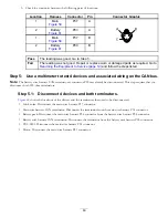
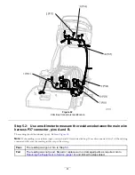
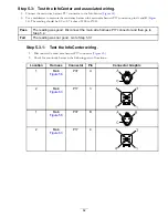
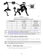
Use a multimeter to test the 2 terminators and associated wiring.
1.
Disconnect the battery pack. Refer to
Disconnecting the Battery Pack (page 17)
.
57

