Fault 09 Internal Motor
InfoCenter Display:
Internal Motor Fault
Fault Description
The motor is monitored for speed and high/low voltage conditions.
Conditions for Setting the Fault
The motor detected an internal fault condition.
Possible conditions for this fault are that the speed-position sensor states are invalid or the motor is detecting an
overvoltage/undervoltage condition. The motor power or the motor logic circuits indicate an overvoltage condition when the
circuit has exceeded 67.5 Vdc and also indicate a motor power undervoltage when the circuit is under 32 Vdc.
Note:
The motor may operate in an unstable condition or stop operating.
Recommended Service Actions
Step 1:
Verify that the fault repeats.
1.
Clear the InfoCenter fault log. Refer to
Clearing the InfoCenter Fault Log (page 19)
.
2.
Disconnect the battery pack for 30 seconds. Refer to
Disconnecting the Battery Pack (page 17)
.
3.
Connect the battery pack. Refer to
Connecting the Battery Pack (page 17)
.
4.
Start and operate the machine. Refer to the
eFlex Operator’s Manual
Pass
The fault did not repeat. Go to
Returning the Equipment to Service (page 19)
and follow the
steps listed.
Note:
If the fault does not repeat, a false detect event may have occurred.
Fail
The fault repeated. Go to step 2.
Step 2:
Check the charge level of the battery.
Check the InfoCenter LCD screen to ensure that the charge level is adequate. If the battery indicator does not show at least 1
full block, connect the battery charger to the battery pack and charge the battery pack to at least 40% capacity.
Step 3:
Remove 2 access covers to aid troubleshooting.
Performing these steps provides access to connectors on the wire harnesses.
1.
Remove the console cover. Refer to
Console Cover (page 19)
.
2.
Remove the power center cover. Refer to
Power Center Cover (page 20)
.
Step 4:
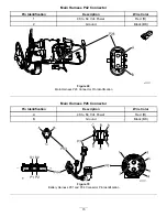
Check for 48 to 64 Vdc at the motor.
Refer to the
eFlex Service Manual
Chapter 4, Electrical System, Main Contactor section for component testing.
1.
Rotate the key switch to the O
FF
position.
2.
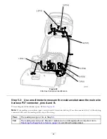
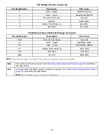
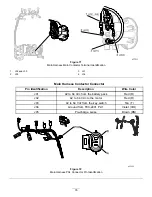
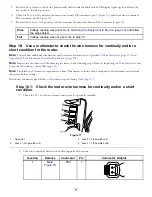
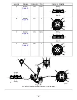
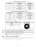
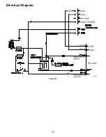
Connect a multimeter between the main contactor, terminal J02/J05 (
), and the main wire harness P04
connector, pin B (
).
75

