2.
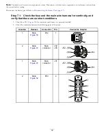
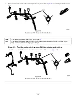
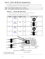
Measure the resistance between pins A and B of the main wire harness CAN terminator. The reading should be
108 to 132 ohms.
A
B
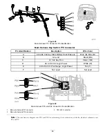
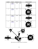
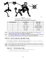
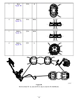
Figure 60
CAN Terminator Pin Identification
3.
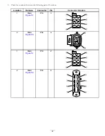
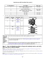
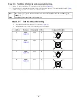
Check for continuity between the following pairs of locations:
Location
Harness
Connector
Pin
Connector Graphic
1
Main
P37
A
2
Main
P14
A
1
Main
P37
B
2
Main
P14
B
B
C
A
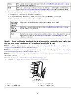
Pass
The continuity readings are good at the listed locations. Connect the main wire harness
CAN terminator to the main wire harness P14 connector. Go to Step
Fail
The continuity readings are not good. Repair or replace worn or damaged parts as
required. Go to
Returning the Equipment to Service (page 19)
and follow the steps listed.
Step 4.2:
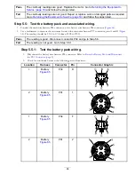
Test the battery wire harness CAN terminator and wiring.
1.
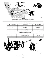
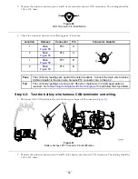
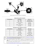
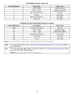
Disconnect the CAN terminator from the battery wire harness P03 connector (
).
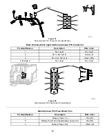
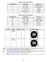
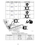
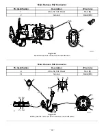
Figure 61
Battery Harness P03 Connector Pin Identification
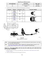
2.
Measure the resistance between pins A and B of the battery wire harness CAN terminator. The reading should be
108 to 132 ohms.
59

