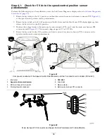

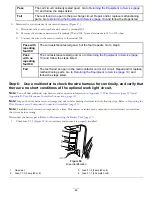


Step 4:
Use a multimeter to perform pre-charge voltage condition checks.
Note:
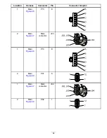
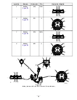
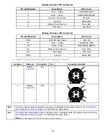
You will find additional wire harness and connector information in
Appendix A: Wire Harnesses (page 113)
and
Appendix B: Toro Electronic Controller Connections (page 135)
.
Note:
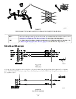
Inspect the wire harnesses for damage and wear while checking the items in the following steps. Refer to
Wire Harnesses and Component Connector Assemblies (page 13)
.
1.
Rotate the key switch to the O
FF
position.
2.
Rotate the key switch to the S
TART
position and hold it there until the InfoCenter LCD display lights up, then release the
key switch to the R
UN
position.
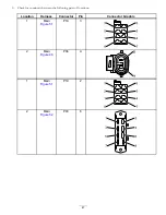
3.
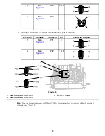
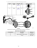
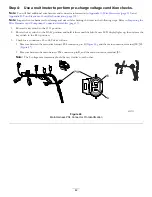
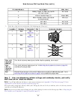
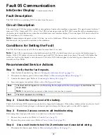
Check for a continuous 42 to 64 Vdc as follows:
•
Measure between the main wire harness P04 connector, pin B (
), and the main contactor, terminal J02/J05
(
•
Measure between the main harness P04 connector, pin B, and the main contactor, terminal J03.
Note:
The 2 voltage measurements should be very similar to each other.
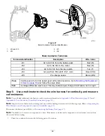
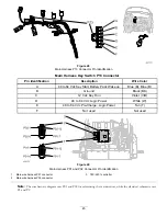
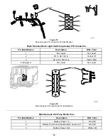
Figure 46
Main Harness P04 Connector Pin Identification
42