10.
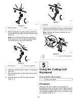
For the front cutting units, slide a cutting unit
under the lift arm while inserting the carrier frame
shaft up into the lift-arm pivot yoke (
g020321
Figure 10
1.
Lift arm
3.
Lift-arm pivot yoke
2.
Carrier frame shaft
11.
Use the following procedure on the rear cutting
units when the height of cut is above 1.2 cm
(3/4 inch).
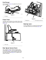
A.
Remove the lynch pin and washer securing
the lift-arm pivot shaft to the lift arm and
slide the lift-arm pivot shaft out of the lift
arm (
).
g003979
Figure 11
1.
Lift-arm shaft lynch pin and washer
B.
Insert the lift-arm yoke onto the carrier
frame shaft (
).
C.
Insert the lift-arm shaft into the lift arm and
secure it with the washer and lynch pin
(
12.
Insert the cap over the carrier frame shaft and
lift-arm yoke.
13.
Secure the cap and the carrier frame shaft to the
lift-arm yoke with the snapper pin.
Note:
Use the slot if a steering cutting unit is
desired or use the hole if the cutting unit is to be
locked in position (
14.
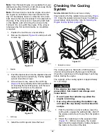
Secure the lift-arm chain to the chain bracket
with the snapper pin (
Note:
Use the number of chain links specified
in the cutting unit
Operator's Manual
.
g003948
Figure 12
1.
Lift-arm chain
3.
Snapper pin
2.
Chain bracket
15.
Coat the spline shaft of the reel motor with clean
grease.
16.
Oil the reel-motor O-ring and install it onto the
motor flange.
17.
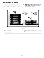
Install the motor by rotating it clockwise so that
the motor flanges clear the locknuts (
). Rotate the motor counterclockwise until the
flanges encircle the nuts, then tighten the nuts.
Important:
Make sure that the reel motor
hoses are not twisted, kinked, or at risk of
being pinched.
g020322
Figure 13
1.
Reel-drive motor
2.
Mounting nuts
14
Summary of Contents for 03820
Page 53: ...Notes ...
Page 54: ...Notes ...


