background image

Tilt-Steering Lever

Pull the tilt-steering lever (

Figure 21

back to tilt the

steering wheel to the desired position. Then push the
lever forward to secure the position.

Ignition Switch

The ignition switch (

Figure 23

), used to start, stop,

and preheat the engine, has 3 positions: O

FF

,

O

N

/P

REHEAT

, and S

TART

. Rotate the key to the

O

N

/P

REHEAT

position until the glow-plug indicator

light goes out (approximately 7 seconds); then rotate
the key to the S

TART

position to engage the starter

motor. Release the key when the engine starts. The
key moves automatically to the O

N

/R

UN

position. To

shut off the engine, rotate the key to the O

FF

position.

Remove the key from the switch to prevent accidental
starting.

g019980

Figure 23

1.

Parking brake

7.

Oil-pressure light

2.

Ignition switch

8.

Temperature light

3.

Enable/Disable switch

9.

Light switch

4.

Diagnostic light

10.

Glow-plug indicator light

5.

Lower mow/raise control
lever

11.

Throttle

6.

Hour meter

12.

Alternator light

Throttle

Move the throttle (

Figure 23

) forward to increase the

engine speed and rearward to decrease the engine
speed.

Enable/Disable Switch

Use the enable/disable switch (

Figure 23

in

conjunction with the lower mow/raise control lever to
operate the cutting units.

The cutting units cannot

be lowered when the mow/transport lever is in the
transport position.

Hour Meter

The hour meter (

Figure 23

) indicates the total hours of

machine operation. The hour meter starts to function
whenever the key switch is in the O

N

position.

Lower Mow/Raise Control Lever

This lever (

Figure 23

) raises and lowers the cutting

units and also starts and stops the cutterheads
when the cutterheads are enabled in the mow mode.

The cutting units cannot be lowered when the
mow/transport lever is in the transport position.

Note:

When the cutting units are enabled, the lever

does not have to be held in the forward position while
the cutting units are lowered or raised.

Engine Coolant Temperature
Warning Light

The temperature warning light (

Figure 23

) glows if

the engine coolant temperature is high. The cutting
units will be disabled. If the coolant temperature rises
another 5.5° C (10° F), the engine will be shut off to
prevent further damage.

Oil-Pressure Warning Light

The oil-pressure warning light (

Figure 23

glows if the

engine-oil pressure drops below a safe level.

Alternator Light

The alternator light (

Figure 23

) should be off when

the engine is running. If it is on, the charging system
should be checked and repaired as necessary.

Glow-Plug Indicator

The glow-plug indicator light (

Figure 23

glows when

the glow plugs are operating.

Parking Brake

Whenever the engine is shut off, engage the parking
brake (

Figure 23

) to prevent accidental movement of

the machine. To engage the parking brake, pull up on
the lever. The engine stops if you press the traction
pedal with the parking brake engaged.

Diagnostic Light

The diagnostic light (

Figure 23

illuminates when a

system fault occurs.

18


Summary of Contents for 03820

Page 1: ...rm No 3412 511 Rev C Reelmaster 3555 and 3575 Traction Unit Model No 03820 Serial No 400000000 and Up Model No 03821 Serial No 400000000 and Up Register at www Toro com Original Instructions EN 3412 511 C ...

Page 2: ...mercial grounds It is not designed for cutting brush mowing grass and other growth alongside highways or for agricultural uses Read this information carefully to learn how to operate and maintain your product properly and to avoid injury and product damage You are responsible for operating the product properly and safely You may contact Toro directly at www Toro com for product and accessory infor...

Page 3: ...ommended Maintenance Schedule s 35 Daily Maintenance Checklist 36 Service Interval Chart 37 Pre Maintenance Procedures 37 Pre Maintenance Safety 37 Removing the Hood 37 Removing the Battery Cover 38 Lubrication 38 Greasing the Bearings and Bushings 38 Engine Maintenance 40 Engine Safety 40 Servicing the Air Cleaner 40 Changing the Engine Oil and Filter 40 Fuel System Maintenance 41 Servicing the F...

Page 4: ... not operate the machine without all guards and other safety protective devices in place and functioning properly on the machine Keep bystanders and children out of the operating area Never allow children to operate the machine Shut off the engine remove the key and wait for all movement to stop before you leave the operator s position Allow the machine to cool before adjusting servicing cleaning ...

Page 5: ...remove the lift arm and pivot yoke decal120 0627 120 0627 1 Cutting dismemberment hazard fan stay away from moving parts keep all guards and shields in place decal93 6688 93 6688 1 Warning read the Operator s Manual before performing maintenance 2 Cutting hazard of hand or foot shut off the engine and wait for all moving parts to stop decal106 6755 106 6755 1 Engine coolant under pressure 3 Warnin...

Page 6: ...99 3444 decal99 3444 99 3444 1 Transport speed 2 Mow speed decal133 4900c 133 4900 1 Read the Operator s Manual 6 ...

Page 7: ...e the ignition key before leaving the machine 2 Warning read the Operator s Manual before towing the machine 5 Thrown object hazard keep bystanders out of the operating area 3 Tipping hazard slow machine before turning do not turn at high speeds lower the cutting units when driving down slopes use a roll over protection system and wear the seat belt 6 Entanglement hazard belt stay away from moving...

Page 8: ... operating the machine on slopes Raising the cutting units while operating on slopes can cause the machine to become unstable 1 Warning read the Operator s Manual do not operate this machine unless you are trained 4 Warning do not park the machine on slopes engage the parking brake lower the cutting units shut off the engine and remove the ignition key before leaving the machine 2 Warning read the...

Page 9: ...tment 3 Read the Operator s Manual for information on adjusting the reel 2 11 blade reel adjustment decal133 4901 133 4901 1 8 blade reel adjustment 3 Read the Operator s Manual for information on adjusting the reel 2 11 blade reel adjustment 9 ...

Page 10: ...n 3 Remove the key from the ignition 4 Engage the parking brake 10 Lights 3 Pull the knob out to engage the cutting units 7 Engine shut off 11 Fast 4 Push the knob in to disengage the cutting units 8 Engine preheat 12 Slow decalbatterysymbols Battery Symbols Some or all of these symbols are on your battery 1 Explosion hazard 6 Keep bystanders away from the battery 2 No fire open flame or smoking 7...

Page 11: ...CE only 5 Cutting unit kickstand 1 Use the cutting unit kickstand Media and Additional Parts Description Qty Use Ignition keys 2 Start the engine Operator s Manual 1 Engine operator s manual 1 Read the manuals before operating the machine Operator training material 1 Review the training material before operating the machine Cutting performance paper 1 Use the paper for adjusting the cutting unit r...

Page 12: ... as follows A Remove the 2 carriage bolts and nuts securing the rod bracket to the cutting unit tabs Figure 4 g003949 Figure 4 1 Turf compensation spring 3 Spring tube 2 Rod bracket B Remove the flange nut securing the spring tube bolt to the carrier frame tab Figure 4 and remove the assembly C Mount the spring tube bolt to the opposite tab on the carrier frame and secure it with the flange nut No...

Page 13: ...Cutting unit 4 g015160 Figure 7 1 Hose guide left side shown 3 Nuts 2 Rod bracket g019602 Figure 8 1 Hose guides each must lean toward the center cutting unit 8 Lower all the lift arms completely 9 Remove the snapper pin and the cap from the lift arm pivot yoke Figure 9 g003975 Figure 9 1 Snapper pin 2 Cap 13 ...

Page 14: ... shaft and lift arm yoke 13 Secure the cap and the carrier frame shaft to the lift arm yoke with the snapper pin Note Use the slot if a steering cutting unit is desired or use the hole if the cutting unit is to be locked in position Figure 9 14 Secure the lift arm chain to the chain bracket with the snapper pin Figure 12 Note Use the number of chain links specified in the cutting unit Operator s M...

Page 15: ...ing rod until the compressed length of the spring Figure 14 is 12 7 cm 5 inches for 5 inch cutting units and 15 8 cm 6 1 4 inches for 7 inch cutting units Note When operating on rough terrain decrease the spring length by 2 5 cm 1 2 inch Ground following will be slightly decreased 3 Installing the CE Decal Parts needed for this procedure 1 Warning decal 120 1686 Procedure If this machine will be u...

Page 16: ...igure 16 6 Hook the latch onto the hood latch bracket Figure 17 g012630 Figure 17 1 Hood latch 7 Screw the bolt into the other arm of the hood lock bracket to lock the latch in position Figure 18 Note Tighten the bolt securely but do not tighten the nut g012631 Figure 18 1 Bolt 3 Arm of hood lock bracket 2 Nut 5 Using the Cutting Unit Kickstand Parts needed for this procedure 1 Cutting unit kickst...

Page 17: ...ward Press the reverse traction pedal Figure 21 to move backward or to assist in stopping when moving forward Also allow the pedal to move or move it to the NEUTRAL position to stop the machine Mow Transport Slide Using your heel move the mow transport slide Figure 21 to the left to transport and to the right to mow The cutting units only operate in the mow position and not lower in the transport ...

Page 18: ...es the total hours of machine operation The hour meter starts to function whenever the key switch is in the ON position Lower Mow Raise Control Lever This lever Figure 23 raises and lowers the cutting units and also starts and stops the cutterheads when the cutterheads are enabled in the mow mode The cutting units cannot be lowered when the mow transport lever is in the transport position Note Whe...

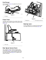
Page 19: ...983 Figure 25 1 Power point Reel Speed Control Knob The reel speed control controls the speed of the cutting units Figure 26 The reel speed increases as you turn the knob counterclockwise Refer to the reel speed chart decal Figure 34 to determine the proper reel speed g020248 Figure 26 1 Backlap lever 2 Reel speed control knob Backlap Lever Use the backlap lever in conjunction with the lower mow r...

Page 20: ...perate or service the machine Local regulations may restrict the age of the operator The owner is responsible for training all operators and mechanics Become familiar with the safe operation of the equipment operator controls and safety signs Shut off the engine remove the key and wait for all movement to stop before you leave the operator s position Allow the machine to cool before adjusting serv...

Page 21: ...ent of 5 or lesser blends in cold weather Monitor seals hoses and gaskets in contact with fuel as they may degrade over time Expect plugging of the fuel filter for a time after converting to biodiesel blends Contact your distributor if you wish for more information on biodiesel 1 Park the machine on a level surface lower the cutting units engage the parking brake shut off the engine and remove the...

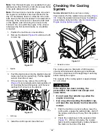
Page 22: ... mark on the dipstick g008882 Figure 29 1 Oil fill cap 5 Install the oil fill cap and close the hood Checking the Cooling System Service Interval Before each use or daily Clean debris off of the radiator oil cooler daily Figure 30 Clean the radiator oil cooler hourly if conditions are extremely dusty and dirty refer to Cleaning the Engine Cooling System page 45 g019984 Figure 30 1 Radiator oil coo...

Page 23: ...weight fluid Pour point ASTM D97 36 7 C to 45 C 34 F to 49 F FZG fail stage 11 or better Water content new fluid 500 ppm maximum Industry Specifications Vickers I 286 S Vickers M 2950 S Denison HF 0 Vickers 35 VQ 25 Eaton ATS373 C The proper hydraulic fluids must be specified for mobile machinery as opposed to industrial plant usage multiweight type with ZnDTP or ZDDP anti wear additive package no...

Page 24: ...ility This could cause a rollover which may result in personal injury or death Do not underinflate the tires Torquing the Wheel Nuts Service Interval After the first hour After the first 10 hours Every 200 hours Torque the wheel nuts to 103 to 127 N m 76 to 94 ft lb WARNING Failure to maintain proper torque of the wheel nuts could result in personal injury Maintain proper torque of the wheel nuts ...

Page 25: ... feet away from the cutting units Look behind and down before backing up to be sure of a clear path Use care when approaching blind corners shrubs trees or other objects that may obscure your vision Stop the cutting units whenever you are not mowing Slow down and use caution when making turns and crossing roads and sidewalks with the machine Always yield the right of way Operate the engine only in...

Page 26: ...use the machine to become unstable Starting and Shutting Off the Engine You may need to bleed the fuel system if any of the following situations have occurred refer to Bleeding the Fuel System page 29 Initial startup of a new engine The engine has ceased running due to lack of fuel Maintenance has been performed upon the fuel system components Starting the Engine 1 Ensure that the parking brake is...

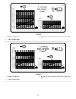
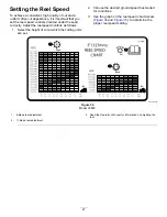
Page 27: ...ntrols as follows 1 Select the height of cut at which the cutting units are set 2 Choose the desired ground speed best suited for conditions 3 Use the graph on the reel speed chart decals Figure 34 and Figure 35 to determine the proper reel speed setting decal121 7884 Figure 34 Model 03820 1 8 blade reel adjustment 3 Read the Operator s Manual for information on adjusting the reel 2 11 blade reel ...

Page 28: ...ar cutting units to compensate for different turf conditions and to maintain a uniform height of cut in rough conditions or in areas of thatch buildup You can adjust each counterbalance spring to 1 of 4 settings Each increment increases or decreases counterbalance on the cutting unit by 2 3 kg 5 lb You can position the springs on the back side of the first spring actuator to remove all counterbala...

Page 29: ...se a funnel and fill the fuel tank outdoors in an open area when the engine is off and is cold Wipe up any fuel that spills Do not fill the fuel tank completely full Add fuel to the fuel tank until the level is 6 to 13 mm 1 4 to 1 2 inch below the bottom of the filler neck This empty space in the tank allows the fuel to expand Never smoke when handling fuel and stay away from an open flame or wher...

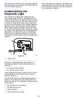
Page 30: ...electrical system The light stops blinking and automatically resets when you turn the key switch to the OFF position once the fault has been resolved g020251 Figure 39 1 Diagnostic light When the controller diagnostic light blinks 1 of the following problems has been detected by the controller An output has been shorted An output is open circuited Using the diagnostic display determine which outpu...

Page 31: ...gaged CAUTION If safety interlock switches are disconnected or damaged the machine could operate unexpectedly causing personal injury Do not tamper with the interlock switches Check the operation of the interlock switches daily and replace any damaged switches before operating the machine Verifying the Interlock Switch Function 1 Park the machine on a level surface lower the cutting units engage t...

Page 32: ...ecessary to toggle between inputs displayed and outputs displayed several times to do the following step To toggle back and forth press the toggle button once This may be done as often as required Do not hold the button 8 Sit on the seat and attempt to operate the desired function of the machine The appropriate output LEDs should illuminate to indicate that the ECM is turning on that function Note...

Page 33: ...e key and wait for all movement to stop before you leave the operator s position Allow the machine to cool before adjusting servicing cleaning or storing it Clean grass and debris from the cutting units drives mufflers cooling screens and engine compartment to help prevent fires Clean up oil or fuel spills Shut off the fuel while storing or hauling the machine Disengage the drive to the attachment...

Page 34: ...2 Before starting the engine close the bypass valve by rotating it 90 1 4 turn Important Do not start the engine when the valve is open 34 ...

Page 35: ...he water separator Clean debris off of the radiator Check the hydraulic lines and hoses Every 25 hours Check the electrolyte level if machine is in storage check every 30 days Every 50 hours Lubricate all bearings and bushings daily when conditions are dusty and dirty Every 100 hours Check the condition and tension of all belts Every 150 hours Change the oil and oil filter Every 200 hours Torque t...

Page 36: ...el Check the hydraulic hoses for damage Check for fluid leaks Check the fuel level Check the tire pressure Check the instrument operation Check the height of cut adjustment Lubricate all the grease fittings 2 Touch up any damaged paint 1Check the glow plug and injector nozzles if starting is hard there is excess smoke or rough running is noted 2Immediately after every washing regardless of the int...

Page 37: ...performing maintenance If the cutting units are in the transport position use the positive mechanical lock if available before you leave the machine unattended If possible do not perform maintenance while the engine is running Keep away from moving parts Use jack stands to support the machine or components when required Carefully release pressure from components with stored energy Removing the Hoo...

Page 38: ...ust be lubricated regularly with No 2 lithium grease Lubricate the bearings and bushings daily when operating conditions are extremely dusty and dirty Dusty and dirty operating conditions could cause dirt to get into the bearings and bushings resulting in accelerated wear Lubricate the grease fittings immediately after every washing regardless of the interval specified The grease fitting locations...

Page 39: ... 4 each refer to Figure 49 g200803 Figure 49 Cutting unit pivots 2 each refer to Figure 50 g020393 Figure 50 Neutral adjust mechanism Figure 51 g008901 Figure 51 Mow transport slide Figure 52 g008902 Figure 52 Belt tension pivot Figure 53 g008903 Figure 53 39 ...

Page 40: ...en outside of primary filter and the canister Note Avoid using high pressure air which could force dirt through the filter into the intake tract This cleaning process prevents debris from migrating into the intake when you remove the primary filter 5 Remove and replace the filter Figure 54 Do not clean the used element because it could damage the filter media g002401 Figure 54 1 Air cleaner cover ...

Page 41: ...es contaminated or if the machine will be stored for an extended period of time Use clean fuel to flush out the tank Inspecting the Fuel Lines and Connections Service Interval Every 400 hours Yearly whichever comes first Park the machine on a level surface lower the cutting units engage the parking brake shut off the engine and remove the key from the ignition switch Inspect the fuel lines and con...

Page 42: ... the mounting surface then rotate it an additional 1 2 turn Bleeding Air from the Injectors Note Use this procedure only if the fuel system has been purged of air through normal priming procedures and the engine does not start refer to Bleeding the Fuel System page 29 1 Park the machine on a level surface lower the cutting units engage the parking brake and shut off the engine 2 Loosen the pipe co...

Page 43: ...e the bottom of the split ring inside each cell Install the filler caps with the vents pointing to the rear toward the fuel tank DANGER Battery electrolyte contains sulfuric acid which is fatal if consumed and causes severe burns Do not drink electrolyte and avoid contact with skin eyes or clothing Wear eye protection to shield your eyes and rubber gloves to protect your hands Fill the battery whe...

Page 44: ...e the machine will move during adjustment 3 Loosen the locknut on the traction adjustment cam Figure 59 g008922 Figure 59 1 Traction adjustment cam 2 Locknut WARNING The engine must be running so that you can make a final adjustment of the traction adjustment cam Contact with hot or moving parts can result in personal injury Keep your hands feet face and other body parts away from the muffler othe...

Page 45: ...engage the parking brake shut off the engine and remove the key from the ignition switch 2 Raise the hood 3 Clean the engine area thoroughly of all debris 4 Clean both sides of the radiator thoroughly with compressed air Figure 60 g019984 Figure 60 1 Radiator 5 Close the hood Brake Maintenance Adjusting the Parking Brake Service Interval Every 200 hours Check the adjustment of the parking brake 1 ...

Page 46: ... bolt securing the brace to the engine and the bolt securing the alternator to the brace B Insert a pry bar between the alternator and engine and pry the alternator outward C When the proper tension is achieved tighten the alternator and brace bolts to secure the adjustment Replacing the Hydrostat Drive Belt 1 Park the machine on a level surface lower the cutting units engage the parking brake shu...

Page 47: ... operate the throttle lever should be 89 N 20 lb Hydraulic System Maintenance Hydraulic System Safety Ensure that all hydraulic fluid hoses and lines are in good condition and all hydraulic connections and fittings are tight before applying pressure to the hydraulic system Keep your body and hands away from pinhole leaks or nozzles that eject high pressure hydraulic fluid Use cardboard or paper to...

Page 48: ...gage the parking brake shut off the engine and remove the key from the ignition switch 2 Disconnect the large hydraulic hose Figure 66 from the reservoir and let the hydraulic fluid flow into a drain pan g020253 Figure 66 1 Hydraulic hose 3 Install the hydraulic hose when hydraulic fluid stops draining 4 Fill the reservoir Figure 67 with approximately 13 2 L 3 5 US gallons of hydraulic fluid refer...

Page 49: ...a piece of a reel or bedknife could be thrown at you or bystanders resulting in serious personal injury or death Inspect the cutting units periodically for wear or damage Use care when checking the cutting units Wrap the blades or wear gloves and use caution when servicing the reels and bedknives Only replace or sharpen the reels and bedknives never straighten or weld them On multi bladed machines...

Page 50: ...lap lever to the R backlap position Figure 69 DANGER Contacting the cutting units when they are moving could cause personal injury To avoid personal injury be certain that you are clear of the cutting units before proceeding 7 With the Mow Transport lever in the MOW position move the Enable Disable switch to the ENABLE position Move the Lower Mow Lift control forward to start the backlapping opera...

Page 51: ... on a level surface lower the cutting units engage the parking brake shut off the engine and remove the key from the ignition switch 2 Thoroughly clean the traction unit the cutting units and the engine 3 Check the tire pressure Inflate all tires to 83 kPa 12 psi 4 Check all fasteners for looseness tighten as necessary 5 Grease or oil all grease fittings and pivot points Wipe up any excess lubrica...

Page 52: ...E 15W 40 motor oil 4 Start the engine and run it at idle speed for approximately 2 minutes 5 Shut off the engine 6 Thoroughly drain all fuel from the fuel tank fuel lines fuel filter and water separator assembly 7 Flush the fuel tank with fresh clean diesel fuel 8 Secure all fuel system fittings 9 Thoroughly clean and service the air cleaner assembly 10 Seal the air cleaner inlet and the exhaust o...

Page 53: ...Notes ...

Page 54: ...Notes ...

Page 55: ...f these activities We will not sell your personal information to any other company We reserve the right to disclose personal information in order to comply with applicable laws and with requests by the appropriate authorities to operate our systems properly or for our own protection or that of other users Retention of your Personal Information We will keep your personal information as long as we n...

Page 56: ...to damage to seats due to wear or abrasion worn painted surfaces scratched decals or windows etc Parts Parts scheduled for replacement as required maintenance are warranted for the period of time up to the scheduled replacement time for that part Parts replaced under this warranty are covered for the duration of the original product warranty and become the property of Toro Toro will make the final...

Reviews: