background image

Control Box

P/N 7010-0344

2-3

The LCD (Liquid Crystal Display)

The LCD allows the operator to view text and graphic symbols that 
represent elevation or slope settings that System Five is currently 
maintaining for the left and right sides of the motorgrader. 

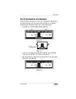
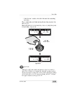
• System Five in Control Mode during operation. 

Figure 2-2.  

Figure 2-3. 

• 2.0% cross slope has been selected for the left side. The blade 

symbol shows that the 2.0% slope is going down. 

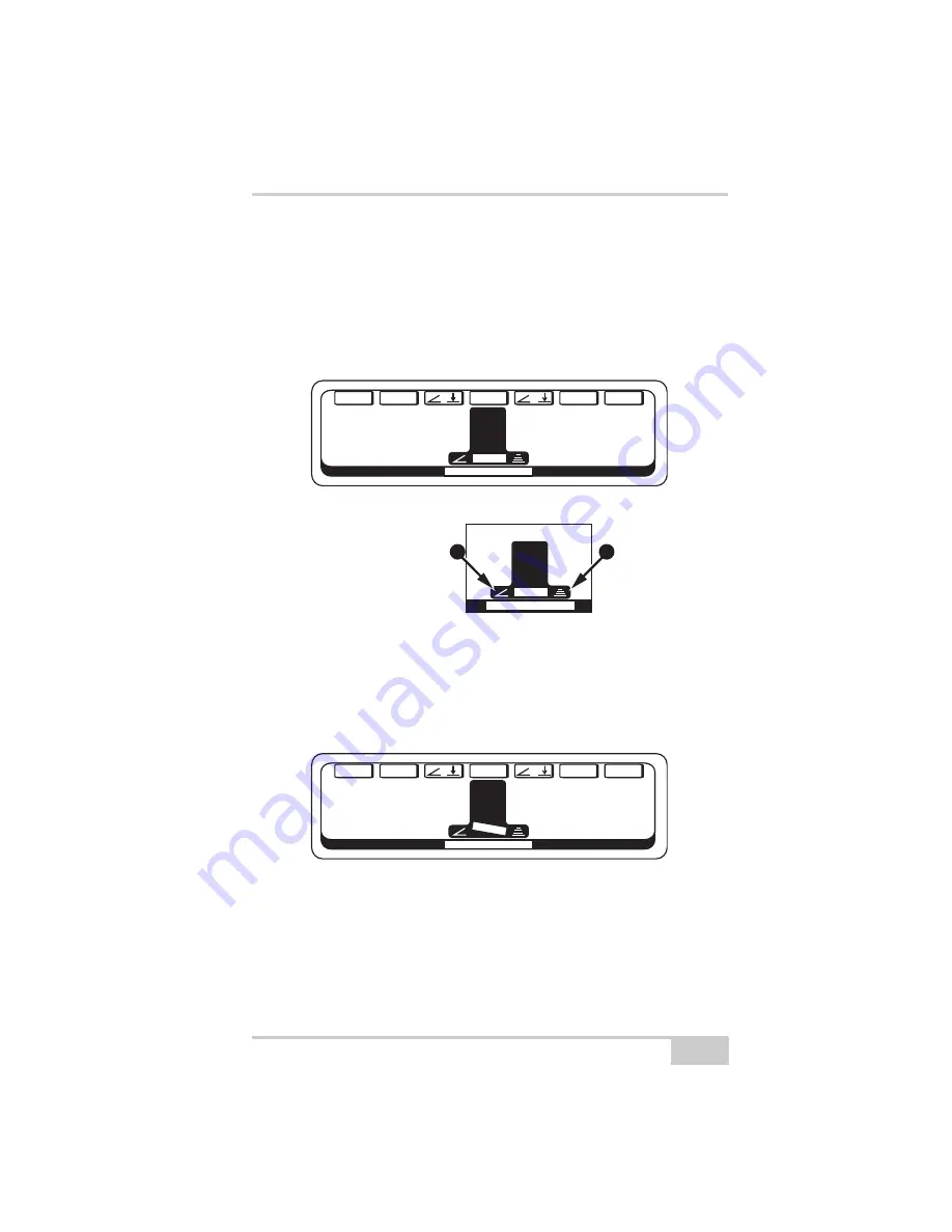
• The Sonic Tracker symbol indicates that Sonic Control has been 

selected for the right side. 

Figure 2-4. 

0.0

F

T

CONTROL MODE

GAIN

SET

/

+

/

/

TRIM

MENU

0.0%

+

LEFT

RIGHT

A

B

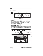
CONTROL MODE

A = Slope Control
B = Sonic Control

0.0

F

T

CONTROL MODE

GAINS

SET

/

+

/

/

TRIM

MENU

2.0%

+

Summary of Contents for Motorgrader

Page 1: ...OTORGRADER 3YSTEM IVE4 ONTROL OX PERATORlS ANUAL...

Page 2: ......

Page 3: ...344 Rev E Copyright Topcon Positioning Systems March 2007 All contents in this manual are copyrighted by Topcon All rights reserved The information contained herein may not be used accessed copied sto...

Page 4: ...ECO 2955...

Page 5: ...e 1 11 Chapter 2 Operation 2 1 Control Box 2 1 Control Box Front Panel Switches and Controls 2 2 The LCD Liquid Crystal Display 2 3 Left and Right Grade Adjustment LEDs 2 4 Left and Right Automatic Op...

Page 6: ...oss Slope Trim Calibration 4 2 Sonic Tracker Setup 4 3 Setting the Reference Number 4 9 Laser Receiver Setup 4 12 Using Set Points 4 18 Chapter 5 Grading Applications 5 1 Sonic Stringline 5 1 Setting...

Page 7: ...and Lubrication 6 7 Cleaning the Rotation Sensor 6 7 Lubricating the Rotation Sensor 6 9 Chapter 7 Troubleshooting 7 1 System Test Mode 7 1 Accessing the System Test 7 2 Slope Sensor Test 7 3 Trouble...

Page 8: ...Table of Contents Motorgrader System Five Operator s Manual Notes iv...

Page 9: ...ur TOPCON System Five Also contained in this manual is a selection of WARNINGS CAUTIONS and NOTICES you should become familiar with to safely operate the system Each symbol represents a particular lev...

Page 10: ...ontained herein are based on the latest available information at the time of publication TOPCON reserves the right to make product changes at any time without notice Comments suggestions and questions...

Page 11: ...n Make faster and fewer cuts No extra passes to check grade Control Material Consistent grade along the entire job not just at the hubs means no filling grade variations with costly base or paving mat...

Page 12: ...em Five Operator s Manual 1 2 Figure 1 1 1 Control Box 2 Laser Tracker Trackerjack 3 Smart Knobs TM 4 Sonic Tracker II TM 5 Slope Sensor 6 Rotation Sensor 7 Manifold Sensor 8 Hydraulic Manifold Assemb...

Page 13: ...t easily attaches to its mounting bracket with one clamp and at the end of the day can be quickly removed for storage The control box connects to the Remote Smart Knobs and the machine power system wi...

Page 14: ...t Knobs mount on the grader s control levers for easy access The knobs allow the operator to perform several Control Box functions while keeping his hands where they belong on the levers Figure 1 3 LE...

Page 15: ...for returned echoes like a microphone The Tracker measures the distance and controls grade from a physical grade reference such as a curb stringline or existing road surface The Sonic Tracker II atta...

Page 16: ...er up the Laser Tracker The Trackerjack attaches to the laser receiver and then mounts onto a vibration pole Use the coil cord from the Sonic Tracker II to power up the Laser Tracker Trackerjack Syste...

Page 17: ...vel sensor within it that functions like a carpenter s level It then relays that information to the Control Box The Blade Slope Sensor will measure slopes from 20 to 20 There is an option for a steep...

Page 18: ...he blade This enables the operator to rotate the blade at any time and System Five will continue to maintain the desired cross slope The Rotation Sensor is a sealed unit and contains no adjustments On...

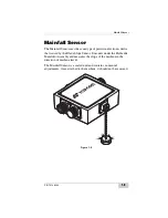
Page 19: ...onic device that is used by the Blade Slope Sensor It mounts under the Hydraulic Manifold Assembly and measures the slope of the machine in the direction of machine travel The Mainfall Sensor is a sea...

Page 20: ...is connected into the grader blade lift cylinders It acts like the manual valves the operator controls by hand automatically raising or lowering the blade to produce desired grade The Hydraulic Manif...

Page 21: ...cords At the end of the day always wipe down each of the components and place them and the coil cords in the appropriate sections for storage This will ensure the continued integrity of these compone...

Page 22: ...System Overview Motorgrader System Five Operator s Manual Notes 1 12...

Page 23: ...n the Control Box Sonic Tracker II s and or cables when being put into the Carrying Case can cause condensation on the inside of the components which may severely affect accurate operation during the...

Page 24: ...isplays located on the front panel of the Control Box The function of each is as follows Figure 2 1 1 LCD Display 2 Left and Right Grade Adjustment LED s 3 Left and Right Automatic Operation Indicator...

Page 25: ...the motorgrader System Five in Control Mode during operation Figure 2 2 Figure 2 3 2 0 cross slope has been selected for the left side The blade symbol shows that the 2 0 slope is going down The Sonic...

Page 26: ...up arrow Slow blinking red up arrow Out of range beyond 2 above grade Above grade between 05 2 Above grade between 02 05 Within 02 of grade On grade Within 02 of grade Below grade between 02 05 Below...

Page 27: ...ight Grade Adjustment Knobs These knobs are used to make measured adjustments to the cross slope or elevation settings Adjusts the grade height when Elevation Control is selected Turning the knob cloc...

Page 28: ...tment Knob to indicate the direction the knob should be rotated to reach On Grade Rotate the knob counter clockwise to reach grade Rotate the knob clock wise to reach grade Figure 2 8 Power Switch Pus...

Page 29: ...always power up in the Control Mode The adjustments and settings will appear just as they were left the last time the box was shut off In order to work in the 3DMC or Setup Mode press the function bu...

Page 30: ...DMC and Setup Modes Elevation Slope Setting Pressing the Elevation Slope button will change the left or right sides of the LCD from Elevation Mode to Slope Mode and vice versa Figure 2 12 0 0 FT CONTR...

Page 31: ...The blade indicator shows the direction of slope Figure 2 14 System System Five Five System Five System System Five Five System Five CONTROL MODE GAIN TRIM TRIM MENU 2 0 CONTROL MODE GAIN TRIM SET ME...

Page 32: ...fly in automatic cross slope operation This calibration should be performed as the cutting edge wears When operating in harsh material conditions the slope calibration should be checked more often Re...

Page 33: ...any value desired This does not change the elevation it only changes the reference number displayed on the Control Box Refer to Setting Reference Number section within this manual Figure 2 16 SET Syst...

Page 34: ...e increase the Gain Setting Number which will cause the hydraulics to respond quicker If the blade is moving too fast and the lights are skipping through On Grade decrease the gain There is a separate...

Page 35: ...ation setting Each time one of the buttons is pressed the slope elevation will change by one step Theoutside button will System System Five Five System Five Auto Auto System System Five Five System Fi...

Page 36: ...lso shows the readings of the Blade Slope Sensor Mainfall Sensor and Rotation Sensor This screen enables the operator to quickly check that all the sensors are functioning To activate the Slope Indica...

Page 37: ...ard when swap occurs Figure 2 20 NOTICE NOTICE Although swap will switch elevation slope from left to right side it does not change the elevation grade setting used previously on that side If the curr...

Page 38: ...MC is a revolutionary new automated machine control system that allows a contractor to guide an earthmoving machine directly from the digital data supplied by engineering firms For the first time ever...

Page 39: ...to be told what changes have occurred on your grader To perform Calibration Settings refer to the Calibration Chapter in this manual Set Points Allows operator to decide how many sets of preset value...

Page 40: ...nished press the EXIT button Figure 2 24 Adjust LED Brightness 1 Press button above BACKLIGHT BRIGHT to brighten up the backlight of the display 2 Press button above BACKLIGHT DIM to dim the backlight...

Page 41: ...ly working Refer to Troubleshooting section Figure 2 26 Beeper Press the ENTER button to toggle between the beeper being ON or OFF When the beeper is turned on a short beep will sound when System Five...

Page 42: ...aker and listens for returned echoes like a microphone The Tracker measures the distance and controls grade from a physical grade reference such as a curb stringline or existing road surface The Sonic...

Page 43: ...sound waves go down bounce off of any physical reference and are reflected back to the Tracker The Tracker measures the time it takes for the sound wave to return to the Tracker Knowing the speed of s...

Page 44: ...Working Window 2 feet above and below the grade reference The grade lights on the Sonic Tracker and Control Box continuously display this grade information to the operator Figure 2 29 Sonic Tracker II...

Page 45: ...above the grade reference Its job is to maintain the exact distance from the tracker to the grade reference keeping the Tracker On Grade If the Tracker is On Grade the cutting edge will be at the desi...

Page 46: ...t to raise the stop watch will be stopped at a longer time The Tracker and Control Box will indicate a down correction arrow and lower hydraulic valve corrections will be applied to bring the Tracker...

Page 47: ...top watch will be stopped at a shorter time The Tracker and Control Box will indicate a raise correction arrow and raise hydraulic valve corrections will be applied to bring the Tracker back to On Gra...

Page 48: ...ingline the Tracker s stopwatch indicates a long time for the sound waves to come back The Tracker is out of the Working Window and no On Grade correction signals will be applied Figure 2 33 Sonic Tra...

Page 49: ...a grade pin the sound waves do not take as long to come back and the stop watch is stopped much sooner The Tracker is out of the Working Window and no On Grade correction signals will be applied Figur...

Page 50: ...ered As an example at about 2 feet from the tracker you will have a footprint or cone of about 6 inches As the Tracker is positioned closer to the grade reference the working footprint decreases in si...

Page 51: ...he grade reference The job application should determine the position of the Tracker For example as a rule of thumb when using a stringline reference keep the Tracker about 2 feet above the string This...

Page 52: ...transmitter is used to produce a plane of light which becomes the grade control reference for the job site The laser receiver will control the blade to cut grade parallel to the laser beam reference...

Page 53: ...Laser Control P N 7010 0344 2 31 As the blade is raised the beam of light hits the Laser Receiver below the center and a lower signal is indicated Figure 2 38...

Page 54: ...Operation Motorgrader System Five Operator s Manual 2 32 As the blade is lowered the beam of light hits the Laser Receiver above the center a raise signal is indicated Figure 2 39...

Page 55: ...l vial which acts as a precision carpenters level As the blade is raised or lowered the Blade Slope Sensor continuously measures the slope of the cutting edge and sends the slope information to the Co...

Page 56: ...es the blade rotation angle to compensate to get the correct cross slope Figure 2 41 Mainfall Sensor Mounted to the frame of the machine is the Mainfall Sensor It has an electronic level vial just lik...

Page 57: ...he edge of the road regardless of the blade angle or going up or down hills The operator can rotate the blade on the fly and System Five will automatically compensate to cut the correct cross slope Fi...

Page 58: ...Operation Motorgrader System Five Operator s Manual Notes 2 36...

Page 59: ...as to be told what changes have occurred on your grader All the Calibration Settings are stored in the Control Box memory The Control Box will not loose the Calibration Settings when turned off or sto...

Page 60: ...hen the blade is perpendicular or at 0 degrees to the A frame assembly Wear or damage to the machine s hose tray or guide rods are the reason for occassional Rotation Sensor Calibration To perform the...

Page 61: ...n for occasional Mainfall Sensor Calibration To perform the Mainfall Sensor Calibration 1 Raise the moldboard so that both sides are a few inches above the ground position the machine on a smooth even...

Page 62: ...the machine around 180 degrees and line up the center of rear tires on previous tire mark Push the ENTER button 4 Wait 5 seconds until you hear a double beep and the calibration is complete Figure 3 6...

Page 63: ...ar is the reason for Blade Sensor Calibration To perform the Blade Slope Sensor Calibration 1 Place the cutting edge of the blade firmly on the ground and mark the location This is position 1 Push the...

Page 64: ...ar a double beep and the calibration is complete Figure 3 8 NOTICE NOTICE This is a rough Blade Sensor Calibration and only needs to be performed when the system is installed or if the Slope Sensor ha...

Page 65: ...stem Five is cutting exactly the way it is supposed to To perform the Blade Wear Calibration 1 Switch either left side or right side to Automatic Control and grade a smooth finish pass at least 50 fee...

Page 66: ...position blade over previous pass With one side in automatic slowly lower the blade and observe to see if the cutting edge matches the previous pass Press the NEXT button Figure 3 10 BLADE WEAR CAL T...

Page 67: ...s the ENTER button and the Blade Trim Calibration is complete Figure 3 11 NOTICE NOTICE After pushing the ENTER button the cutting edge and will raise or lower half the distance you just dialed in to...

Page 68: ...inches above the ground 2 Push the Auto Offsets button System Five will automatically perform the Valve Calibration first with left hand raise and then lower then repeating with the right hand side 3...

Page 69: ...knob raising or lowering the Lower Offsets until the left hand side of the blade raises slowly 3 Repeat on the right hand side for both the Raise and Lower Offsets 4 Press the ENTER button and the va...

Page 70: ...Switch OR SmartKnobs Figure 3 14 SmartKnob Selects program to operate the SmartKnob Simple Switch Selects program to operate the Simple Switch System Four Type Switches Auto Select Automatically deter...

Page 71: ...tors Figure 4 1 When you power up System Five it will automatically come on to Control Mode with the settings just as you had them the last time the box was used The Slope Calibration and Elevation Re...

Page 72: ...ly rough you may need to back up and grade 2 or 3 passes until you cut a smooth finish pass 2 Turn the machine around push the switch to reverse the slope and begin to grade slowly over the previous p...

Page 73: ...rst connect the coil cord to the Tracker Bolt the Tracker to the bracket and visually check to get the L Bar and Tracker plumb Make one wrap of the coil cord around the L Bar This will act as a strain...

Page 74: ...tracking a curb keep the L Bar in close to keep the Tracker over the lip of the curb Raise or lower the Tracker bracket to position it at a proper height above the grade reference Although the Tracke...

Page 75: ...losest the Tracker can be set to the grade reference is 14 inches Figure 4 5 The farthest the Tracker can be set from the grade reference is 55 inches Figure 4 6 14 0 MINIMUM DISTANCE Sonic Tracker II...

Page 76: ...tring At 24 inches the Sonic Footprint is about 6 inches in diameter so keeping the Tracker over the string is easy Just keep the moldboard at the edge of the road where it should be and the Tracker s...

Page 77: ...xt to a barrier wall lower the Tracker to reduce the size of the Sonic Footprint Position the Tracker so it just picks up the edge of the road and does not hit the side of the barrier wall The concret...

Page 78: ...perator s Manual 4 8 When tracking a curb lower the tracker so it is just picking up the lip of the curb This will keep it from picking up the top of curb or obstructions in the gutter Figure 4 10 Fig...

Page 79: ...hing a pass the number reads 0 00 In this case the blade is not cutting or filling so it makes sense that the number reads 0 00 To set the reference number 1 Manually place the blade so the cutting ed...

Page 80: ...Control Mode Repeat these steps for the Sonic Tracker on the other side Figure 4 15 System System Five Five System Five Auto Auto CONTROL MODE Gains SET TRIM MENU 0 0 0 0 FT SET ELEVATION RIGHT ENTER...

Page 81: ...the edge For best results switch to Automatic and grade a short pass Look about 18 inches in from the end of the blade to verify whether the cutting edge is matching Make grade adjustments as needed...

Page 82: ...o the L Bar and visually check to get the L Bar and vibration pole plumb To attach the Trackerjack turn on the Control Box and attach the coil cord to the Trackerjack Place the Trackerjack on the vibr...

Page 83: ...the vibration pole acts as an upper limit keeping the Trackerjack from climbing off the top of the pole Position the L Bar horizontally so that the Laser Trackerjack is near the end of the moldboard...

Page 84: ...ce number so that when the cutting edge is at Finished Grade the reference number is either set to a known elevation or set to 0 00 To set the reference number first set up the Laser Transmitter for t...

Page 85: ...On Grade signal This can be done by just pushing the two red buttons on the Smart Knobs and the Trackerjack will search up and down the vibration pole and lock onto the laser beam Figure 4 21 Switch t...

Page 86: ...of 325 65 feet for example then set the display to read 5 65 feet In this case the operator can just dial in a desired elevation This is great when cutting multiple pads at different elevations Push...

Page 87: ...de then set the display to read 15 feet The operator can then dial in a desired height above grade while roughing in then dial down to 0 00 for finish grade Push the SET button turn the knob to read 0...

Page 88: ...The Control Box will automatically remember the settings just as you left them before you switched Refer to the Set Points section within this manual To set up System Five to use Set Points go to the...

Page 89: ...s might be used let s look at a simple job application using two Set Points For this pass the right side is set to Sonic Tracker Control to cut 1 90 below the stringline The left side is set for a 2 0...

Page 90: ...Getting Ready to Grade Motorgrader System Five Operator s Manual 4 20 Figure 4 30 VIEW FROM BEHIND GRADER 2 0 SLOPE CUT GRADE 1 90 BELOW THE SONIC STRINGLINE...

Page 91: ...the cross slope at and the cross slope to 2 0 Figure 4 31 HOLD FOR 1 SECOND RIGHT SIDE SMART KNOB MATCH THE PREVIOUS PASS VIEW FROM BEHIND GRADER 2 0 SLOPE System System Five Five System Five Auto Aut...

Page 92: ...TROL MODE GAINS SET TRIM MENU 95 FT 2 0 CONTROL MODE GAINS SET TRIM MENU 1 00 FT 1 95 FT CONTROL MODE GAIN SET TRIM MENU 2 0 1 2 CONTROL MODE CONTROL MODE Gains SET TRIM MENU 0 0 0 0 FT 2 0 CONTROL MO...

Page 93: ...e information for the operator This information needs to be transferred from the ground to the operator This is commonly done by a grade setter using a hand level a 4 man crew pulling a string across...

Page 94: ...al reference for the job Any mistakes in a hub elevation can be quickly spotted by just sighting down the string NOTICE NOTICE Although Topcon s Sonic Tracker will work with many sizes and types of st...

Page 95: ...44 5 3 1 Place the Sonic Grade Clips on stakes and drive the stakes approximately 6 to 8 inches away from but in line with the hubs Do Not disturb the hubs Figure 5 2 6 0 to 8 0 HUB ALIGN STAKES WITH...

Page 96: ...the working area and pull the stringline tight 3 After the stringline has been pulled tight place it into the fingers of each Sonic Grade Clip Figure 5 3 4 Decide what the Sonic Stringline hike up the...

Page 97: ...int you marked Figure 5 4 5 Next set the cut fill lath on the hub and read the cut or fill from the grade stake next to the hub Adjust the clip up or down until the stringline crosses the cut fill lat...

Page 98: ...cations Motorgrader System Five Operator s Manual 5 6 The stringline is now set to 2 feet above finished grade Figure 5 6 Repeat this process at each station before starting to grade Figure 5 7 2 0 OF...

Page 99: ...he string at the desired hike up as shown in the previous pages Next raise or lower the stringline to compensate for the slope and the distance from edge of the road to the stringline RISE RUN If the...

Page 100: ...more practical to secure the stringline directly to the grade stake next to the hub First mark the lath with a 2 or 3 feet hike up or boot above grade just as you would to check grade with an eye lev...

Page 101: ...line tight At each station staple or ty rap the stringline directly to the witness lath so the stringline is at the desired hike up Figure 5 11 Due to the height of some stakes the Tracker may need to...

Page 102: ...the Sonic Stringline is a predetermined hike up above Finished Grade a simple tool called a Grade Checking Lath can be constructed This can be easily done using lath a level bubble and simple hand to...

Page 103: ...the graded area so that the level bubble extends over the Sonic Stringline shown below Figure 5 13 Tilt the Grade Checking Lath until the level bubble is centered Finished Grade is correct when the l...

Page 104: ...the grade behind the grader and make adjustments if necessary Although this can be done by various methods the Laser Grade Checking System is a quick accurate one person grade checking tool It allows...

Page 105: ...y cuts or fills are immediately measured on the lath or folding rule Figure 5 15 Grade can be inspected at the 1 4 crown centerline or any desired distance Just measure the distance from the edge of t...

Page 106: ...ad and to even verify that the hub or stringline on the opposite side is correct Figure 5 17 To check grade at additional stations just pick up the laser and move it Because of the consistent grade cu...

Page 107: ...een set 2 0 above the desired finished sub grade Desired cross slope is 2 0 Figure 5 19 NOTICE NOTICE Before grading always make sure the Cross Slope System is calibrated and the Tracker reference num...

Page 108: ...5 16 When beginning to cut grade it is likely that the rough subgrade is several inches above grade To start set the cutting edge down on the existing grade with the Tracker positioned over the string...

Page 109: ...Control Box will then read the depth of cut below the stringline at that location In this example the display indicates that the cutting edge is 1 65 feet below the stringline Since the desired depth...

Page 110: ...sing the Smart Knob which will keep your hands on the controls You may want to dial in a small amount of cut as you make this first pioneering pass Depending upon the material conditions and amount of...

Page 111: ...the grade will be consistently a few hundreths high or low By checking the grade and knowing how high or low the grade is being cut adjustments can be made to get the desired grade Figure 5 23 After g...

Page 112: ...ight Tracker is always used On the job the blade can be rotated and the Tracker or slope can be used on either side depending on what is best for that particular job This avoids backing up to use the...

Page 113: ...was cut at 1 70 feet dialing to 1 80 would produce a 10 foot cut With the cross slope system maintaining a 2 0 slope the ENTIRE moldboard will be cutting 10 foot Machine and material conditions will d...

Page 114: ...ntinue to make additional passes until you reach desired grade Figure 5 28 0 00FT CONTROL MODE GAIN SET TRIM MENU 2 0 VIEW FROM BEHIND GRADER 2 0 SLOPE SONIC STRINGLINE 2 00FT CONTROL MODE GAIN SET TR...

Page 115: ...e material on this side of the road at least 1 1 2 2 feet past the centerline Figure 5 30 0 00 FT CONTROL MODE GAIN SET TRIM MENU 2 0 VIEW FROM BEHIND GRADER 2 0 SLOPE SONIC STRINGLINE C L 0 00 FT CON...

Page 116: ...th spray paint to make it visible for the operator Figure 5 31 Finished grade can be carried over the centerline by tracking the pass on the opposite side Figure 5 32 C L 2 0 SLOPE 2 0 SLOPE MARK CENT...

Page 117: ...m the leading edge rotate the moldboard to a fairly steep angle Figure 5 33 Change the direction of the cross slope and switch the cross slope to Automatic Control Then manually lower the leading edge...

Page 118: ...acker to On Grade Since the Tracker is tracking the ground sloping down the opposite side the reference number will not be 0 00 Switch to Automatic Control and continue grading Verify the grade and ma...

Page 119: ...ll cause the Tracker to ride up or ride down the slope causing an elevation error at the centerline Keep the front tire at the same position referencing the centerline paint marks Figure 5 36 Once cen...

Page 120: ...cut by System Five can be used as a reference for the Tracker In this case rotate the blade so that the cross slope is controlling the leading edge of the blade at the edge of the road and the tracker...

Page 121: ...de on a smooth previously graded pass so that the cutting edge is just touching the ground Figure 5 40 Slide the L bar out and rotate it forward to a position where the Tracker will not pick up the wi...

Page 122: ...ator s Manual 5 30 Set the Tracker to on grade and grade the pass along the edge of the road Figure 5 42 Figure 5 43 Sonic Tracker II 2 0 SLOPE RIGHT SONIC STRINGLINE VIEW FROM BEHIND GRADER 2 0 SLOPE...

Page 123: ...Street design varies greatly so use this as an example and make adjustments for your job Figure 5 45 For best results set Sonic Stringline to use as a reference for the sidewalk grade Using Sonic Tra...

Page 124: ...ext pass Figure 5 46 Once the sidewalk grade has been cut and verified mark the edge of the sidewalk with spray paint to make it visible for the operator Figure 5 47 VIEW FROM BEHIND GRADER LEFT SONIC...

Page 125: ...desired grade and slope Figure 5 48 For best results stay about 6 inches in from the paint marks on the rough in passes to avoid material spilling onto the sidewalk grade Figure 5 49 0 75 FT CONTROL M...

Page 126: ...t with spray paint to make it visible for the operator Figure 5 50 Use the curb grade as a reference to cut the street grade Dial in thedesired grade and slope Figure 5 51 MARK EDGE OF STREET WITH SPR...

Page 127: ...void material spilling onto the curb grade Continue to grade the street across the centerline Grade the opposite sidewalk curb and street section and the project is complete Figure 5 52 SONIC STRINGLI...

Page 128: ...position the Tracker to cut from a curb Dial in the slope and desired depth of cut and begin grading from the curb Be sure the grade checker verifies the grade the first 25 50 feet Remember it is alwa...

Page 129: ...terline and then cut the opposite side of the street Figure 5 55 Figure 5 56 0 0 FT CONTROL MODE GAIN SET MENU 2 0 TRIM C 2 0 SLOPE 17 2 BELOW EDGE OF CURB L 0 12 FT CONTROL MODE GAIN SET MENU 2 0 TRI...

Page 130: ...r the windrow has been picked up make a final clean up pass using a Sonic Tracker on each side to complete the project Figure 5 58 0 14 FT CONTROL MODE GAIN SET MENU 2 0 TRIM C 2 0 SLOPE 17 2 BELOW ED...

Page 131: ...e curbs are at different elevations it is impossible to grade a typical design slope on both sides of the street Depending upon the severity of the error in the curbs standard grading practices if Sys...

Page 132: ...centerline Figure 5 61 The curb elevations can be easily spot checked using a fast leveling RL HB rotating laser Set the laser at the lip of one curb then use the detector and a folding rule to take a...

Page 133: ...de from uneven curbs there are two suggested methods Method 1 Using Sonic Tracker and Cross Slope cut grade from one curb highest curb if known and carry grade past centerline Figure 5 63 Use Sonic Tr...

Page 134: ...t grade from the opposite curb Figure 5 65 Use Sonic Tracker and Sonic Tracker to match grade and finish the street Figure 5 66 Method 2 For this method blue tops will need to be set at the centerline...

Page 135: ...e blue tops and use cross slope on the trailing edge leaving the windrow on this side of the street Figure 5 68 Use Sonic Tracker and Cross Slope to match the centerline grade Figure 5 69 Use Sonic Tr...

Page 136: ...Slope System can be used to cut grade from an existing road surface for lane extensions or shoulders If a barrier wall is being used make sure the base of the barrier is at least 2 3 inches from the e...

Page 137: ...ial in the desired depth and slope Figure 5 72 If the barrier wall is placed so close to the edge at the road that the existing surface can not be tracked set up a Sonic Stringline Figure 5 73 2 0 SLO...

Page 138: ...or use short pins welded to a plate to set the stringline Figure 5 74 Grading On Curves The Cross Slope System always cuts the desired slope perpendicular to the graders draw bar assembly of the A fra...

Page 139: ...w bar assembly is perpendicular to the direction of slope Because the Mainfall Sensor is not measuring in the direction of travel there may be a small error in the slope cut After roughing in straight...

Page 140: ...e key to making this job easy is to mark the stations with he Cross Slope so the operator can see the slope at least one station ahead Making the slope on a plastic coated paper plate and stapling the...

Page 141: ...ollowing procedures will ensure trouble free operation 1 Keep the Carrying Case clean and dry Do not leave it open and exposed to the elements Clean and dry all components prior to placing them into t...

Page 142: ...e Sonic Tracker 1 Hold the Sonic Tracker II in an UPRIGHT position this will prevent moisture from inadvert ently entering the Sonic Tracker 2 Mix a mild detergent with water and place the mixture in...

Page 143: ...onic Tracker II to see the ground but not a Sonic Stringline Sonic Tracker II Transducer Replacement 1 Remove and discard the Filter Foam a new Filter Foam is provided in the Transducer Replacement Ki...

Page 144: ...ay loose there elasticity due to weather or exposure to diesel fumes 3 The Transducer can now be gently pulled out Use a SMALL pair of dikes to gently cut the Ty Wrap then remove the small wire connec...

Page 145: ...nto the extra deep area of the recess Place the new O ring around the Transducer and seat firmly between the Transducer and the Sonic Tracker II Transducer recess Figure 6 5 6 Place the black Retainin...

Page 146: ...and may crack the Retaining Ring Use of the O Ring assures tightness while preventing vibration from loosening the Mounting Screws NOTICE NOTICE DO NOT use Loctite on the mounting screws Loctite will...

Page 147: ...NOTICE Cleaning and lubrication of the Rotation Sensor may need to be more frequent if operating in excessively dusty or gritty materials Cleaning the Rotation Sensor The following procedures detail...

Page 148: ...tation Sensor from its base plate Figure 6 9 NOTICE NOTICE DO NOT force or pry the Rotation Sensor from the base plate The Rotation Sensor pin may bend or break 5 Use a clean rag and thoroughly clean...

Page 149: ...pin cavity with fresh grease Figure 6 10 2 Place the Rotation Sensor back on the base plate Make sure the rotation pin seats firml in the pin cavity it will only seat correctly one way Figure 6 11 PAC...

Page 150: ...arm with the L bracket and replace the shoulder screw washer and jam nut Tighten until firm Figure 6 13 Before returning the Rotation Sensor to work the Rotation Sensor must be re calibrated Follow t...

Page 151: ...lem with a cable or system component The following sections will explain how to use the System Test features in order to locate where a problem exists while in the field NOTICE NOTICE Before assuming...

Page 152: ...em Sensor readings are displayed in the center of the LCD Each component should have a number or indicator next to it showing that it is communicating to the Control Box If a component has ERROR displ...

Page 153: ...rated value of the Blade Slope Sensor To check if the sensor is working properly 1 Slowly raise the right side of the blade The slope value should increase smoothly and continuously Figure 7 2 ENTER E...

Page 154: ...ur Slope Sensor is not working properly if The numbers increase or decrease erratically as the blade is smoothly raised and lowered The number displayed continues to change even though you have stoppe...

Page 155: ...nstrument to calculate slope proceed to step 6 Figure 7 4 2 Place the cutting edge lightly on the ground in the same direction you measured the slope The value displayed on the screen should be within...

Page 156: ...ightly place cutting edge in the exact same place The slope value should be in the opposite direction and within 2 of the previous number Figure 7 7 ENTER EXIT KNOB VALUE LASER SONIC KNOB VALUE LASER...

Page 157: ...off 2 At the Mainfall Sensor disconnect the cable from the Control Box 3 Connect the Control Box cable directly into the Blade Slope Sensor You will need to unbolt the Blade Sensor and hold it near th...

Page 158: ...Rotation Sensor Cable is damaged If ERROR is NOT displayed then the failure is located in the Rotation to Blade Slope Sensor Cable If a Blade Slope Sensor or cable failure has occured contact your Top...

Page 159: ...D should display the same slope as in step 1 but in the opposite direction Figure 7 10 If two different slopes are displayed If the second slope displayed is different from the first recalibrate the M...

Page 160: ...rotation rather than percentage of slope NOTICE NOTICE The Rotation Sensor information is communicated to the Control Box from the Slope Sensor If the Slope Sensor or Slope Sensor Cable is defective t...

Page 161: ...cle back until the chisel mark is in line with the A frame and stop Figure 7 13 NOTICE NOTICE If you go past the chisel mark repeat the procedure beginning with the circle rotated 1 foot beyond the ch...

Page 162: ...1 foot from the front tire The value next to Rotation should display the increase from 0 degrees to 45 degrees in a smooth transition If the numbers jump erratically as the circle is being rotated the...

Page 163: ...not refer to the procedures in step 4 Figure 7 16 6 The Rotation Sensor Test can also be used to indicate whether servicing of the circle hose tray or guide rods is required Rotate the circle counter...

Page 164: ...he following Figure 7 19 Excess slop in the pin between the grader s hydraulic swivel and the hose tray Hose tray is bent and the guide rods are no longer attached to the circle The hole where guide r...

Page 165: ...information before installing or using your TOPCON System Five 2 Use extreme caution on the jobsite Working around heavy construction equipment can be dangerous 3 DO NOT attach System FiveD brackets...

Page 166: ...aser beam or view the beam directly with optical equipment 9 Use appropriate welding precautions and practices when welding After welding all affected areas should be painted with a rust inhibitor NOT...

Page 167: ...n adversely affect components If moisture does enter the Carrying Case leave it open and alllow it to thoroughly dry before storing any components 10 To prevent vandalism or theft do not leave removab...

Page 168: ...Safety Information Motorgrader System Five Operator s Manual Notes A 4...

Page 169: ...y be shipped to TOPCON for repair TOPCON will promptly repair the defective item at no charge and ship it back to you Calibration of components labor and travel expenses incurred for in field removal...

Page 170: ...uch damages Service Information Service assistance can be provided by contacting your local TOPCON dealer or by calling the Corporate Service Center Phone 800 443 4567 8 a m to 5 p m Pacific Time Mond...

Page 171: ......

Page 172: ...c 7400 National Drive Livermore CA 94551 U S A Phone 925 245 8300 Fax 925 245 8583 www topcon com 2007 Topcon Positioning Systems Inc All rights reserved No unauthorized duplication P N 7010 0344 Rev...

Reviews: