3-3
Maintenance
reverts to an energy-conserving low
pressure and volume output when no
hydraulic flow is being requested.
1.
Install flow limiter in motor inlet. This
type of flow limiter, (also called a
velocity fuse) protects the hydraulic
motor from over-speeding by shutting
off the flow of oil if the flow rate
exceeds a predetermined amount.
NOTE:
If necessary, the flow limiter can
be reset by placing the hydraulic circuit in
FLOAT to remove all pressure. Reduce
hydraulic flow setting before restarting.
2.
Connect hydraulic hoses to tractor
as described in the OPERATION
SECTION of this manual.
3.
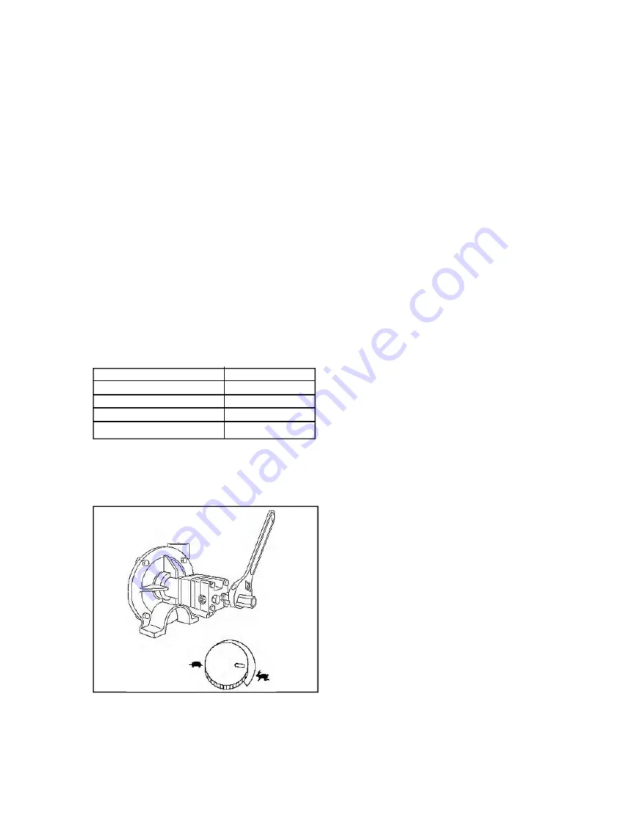
Close motor needle valve by
loosening jam nut, screwing needle
valve clockwise until seated, then
tightening lock nut.
4.
Adjust tractor flow control to its
minimum setting.
5.
Move hydraulic lever to RETRACT
to start pump.
6.
Close
AGITATION CONTROL
valve
after pump primes and begins to
develop pressure.
7.
Adjust tractor flow control until the
desired pressure is reached, up to a
maximum pressure of 120 psi.
IMPORTANT:
Do not run pump for
extended periods with outlet flow fully
blocked. Overheating and pump
damage can result.
The hydraulic driven spray pump is
adaptable to three different types of
tractor hydraulic systems. Use the
following guidelines to assist with setting
the pump for proper operation.
Before starting the setup procedure,
ensure that the solution tank contains at
least 50 gallons of liquid, and the control
valves are at the following settings:
PUMP INLET SELECTOR
<SOLUTION TANK>
INDUCTOR MIX (OPT)
<OFF>
FILTER PURGE CONTROL
<OFF>
PUMP OUTLET SELECTOR
<BOOM>
AGITATION CONTROL
<PARTIALLY OPEN>
SPRAYER PUMP SETUP
NOTE:
The information in this section
pertains explicitly to the Ace brand hydrau-
lic driven spray pumps. While set-up for
Hypro pumps is similar to the Ace set-up
please refer to exact Hypro manual for
specific instructions.
This type of system is most commonly
found on new, larger horsepower tractors.
It is characterized by use of a variable-
displacement hydraulic pump, which
•
Load Sensing Closed-
Center System
Summary of Contents for TA1200
Page 4: ...4 Introduction NOTES...
Page 48: ......
Page 50: ......
Page 51: ...3 23 Maintenance Electrical 401963 Serial B20630210 Lower Revised011405...
Page 52: ...3 24 Maintenance Electrical 401963 Beginning Serial B20630210 Revised011405...
Page 55: ...4 1 Set Up SECTION IV SET UP BOOM REST INITIAL SET UP 4 2...
Page 63: ...5 7 Parts NOTES...
Page 64: ...5 8 Parts Revised011405 401940 WHEELS TIRES...
Page 68: ...5 12 Parts FRAME ATTACHMENTS 401934 Revised011405...
Page 70: ...5 14 Parts PLATFORM RAILINGS 401935 Revised011405...
Page 74: ...5 18 Parts 401936 MAIN TANK...
Page 77: ...5 21 Parts NOTES...
Page 81: ...5 25 Parts PLUMBING OVERHEAD LAYOUT 401971...
Page 84: ...5 28 Parts NOTES...
Page 86: ...5 30 Parts 401986 ELECTRIC CONTROLS OPTIONAL Revised011405...
Page 89: ...5 33 Parts NOTES...
Page 90: ...5 34 401942 INDUCTOR PLUMBING OPTIONAL December 2012...
Page 92: ...5 36 INDUCTOR MOUNTING OPTIONAL 401942 5 40 INDUCTOR MOUNTING OPTIONAL 401942 December 2012...
Page 96: ...5 40 Parts 401972 FOAM MARKER ASSEMBLY...
Page 101: ...5 45 NOTES December 2012...
Page 102: ...PRINTED IN USA TC MANUALS 402061 DECEMBER 2012 3...


