background image

34 


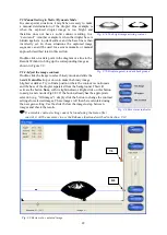
9.13 Base Line determination  

A water droplet applied on a reflecting background will appear as a dark ’saucer’ when the contact 
angle is below 90 degrees. A high contact angle above 90 degrees will appear as a ’black snowman’ 
with a waist against the white background. Similarly a contact angle of 90 degrees will result in a 
black circular shape. All these droplet silhouettes will be analysed automatically and the program will 
assign a base line at the interface between the droplet and the test surface. The determined base line is 
displayed as a dotted line in the captured image. The base line can be adjusted manually as described 
in Section 9.5.2. 


By definition, the base line is the lowest section of the droplet resting on top of the test surface. 


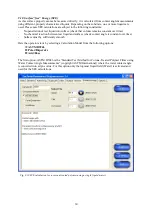
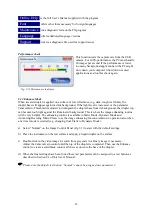
9.14 Camera Gain and Threshold  


The default value for Camera Gain and Threshold is established during calibration. This light level 
determines if a pixel is black or white in the binary image. These values can be modified by the 
operator to manage unusually bright or dark test surfaces as part of a test profile stored under a button 
on the Image Control Panel (Section 9.1). 
 

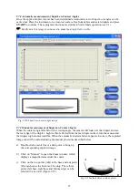
9.15 Field of View limitations 

The measurement of very low contact angles is limited by the horizontal field of view.  
A standard PGX+ instrument has a horizontal view of approximately 6.5 mm. Droplets of 0.5 µL will 
reach a width of 3.7 mm at a contact angle of six degrees. At an angle of 2.5 degrees this droplet will 
have a width of five mm. In comparison a 0.25 µL droplet will reach a width of 4.6 mm at a contact 
angle of 1.5 degrees. As we cannot expect the droplet to be perfectly centred in the image, a useful 
width is some 4.5 mm at the droplet base. This means 0.5µL droplets can be measured down to 3 
degrees.  Similarly, a 0.25 µL droplet can be measured down to a contact angle of 1.5 degrees. For 
even lower contact angles, the droplet volume has to be decreased further (see “Small droplets” in 
Appendix D). 

 
9.16 Use of other test liquids for determination of  ‘Surface “Free” Energy’ 

The PG program has been configured for use with water, Diiodomethane and Formamide in order to 
determine the SFE values. This set of liquids is commonly used and in general there should be no 
reason to select another set. By using this recommended set of liquids your SFE values can be 
compared with other test laboratories using the same set. If you need to use another set of test liquids 
or translate the liquid names to another descriptor name, you can do so in the following way: 
 
a)


Make a backup copy of the file \fibro\bin\SFE.INI 

b)


Open the file SFE.INI with a regular text editor (e.g. NOTEPAD.EXE)  

c)


You may translate the descriptor for water (e.g. ‘Wasser’) but DO NOT change the parameters for 
water, as this will ruin the ASTM D5946 standard for corona treated polymers.  

d)


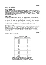
You may change the parameters for the second and third liquids as shown in the example below: 
  

Current   

     New 


Explanation


Formamide 

Ethylene glycol 

Descriptor name 

    58  


     48 


Total surface tension 

TOT


    39 


     29 


Dispersive component 

LW


   2.28 


    1.92 


Basic component 



-


   39.6 


     47 


Acidic component 



+


Static contact angle results will still be stored as wgs, dgs and fgs files even if the liquid parameters 
have been changed. To keep track of files before and after a liquid change it is recommended to 
rename the old results directory or to move old contact angle results to a different directory each time 
a liquid parameter is changed. 


 PLEASE NOTE: SFE calculations done with one set of liquids CANNOT be compared to  

                                    SFE results calculated from another set of liquids; 

Summary of Contents for PGX+

Page 1: ...T Th he e P PG GX X M Me ea as su ur ri in ng g H He ea ad d User s Manual Program version 4 0...

Page 2: ...2...

Page 3: ...cing Mode 9 7 SuperLow contact angles 9 8 View Mode 9 9 Surface Tension 9 10 Surface free Energy SFE 9 11 Options Screen 9 12 Enhance Mode 9 13 Baseline Curtain settings 9 14 Camera Gain Threshold 9 1...

Page 4: ...cal requirements This version of the PGX software can be installed under the following operating systems Windows 10 Windows 8 Windows 7 32 64 bit Windows XP Vista 32 64 Please note the PGX instrument...

Page 5: ...r on the screen c Finally a message may appear This system must be restarted to complete the installation Press OK to continue d Connect the PGX instrument to the USB port you wish to use e Start the...

Page 6: ...rument sole The calibration plate has a similar mark indicating the full sphere Place the PGX instrument on top of the calibration plate with its reference mark positioned above the dot as indicated i...

Page 7: ...displayed in red the instrument must be re calibrated Section 4 1 An optional way to validate the instrument is to place the instrument on top of the calibration plate and perform a measurement in St...

Page 8: ...e test might require special arrangements like a fixture into which the test specimen can be inserted One example is a metal can or a round glass bottle where it will be necessary to position the drop...

Page 9: ...ilitre syringe with the RED tip to fill the container with distilled water DO NOT use tap water as this will leave residuals inside the liquid system c Insert the RED dispensing tip into the air hole...

Page 10: ...m or warping materials e g newsprint cigarette tipping paper should be mounted on top of a flat backing material using a soft sticky adhesive material 6 2 Setting up a test a Check the liquid containe...

Page 11: ...the empty container c Blow liquid container dry with air d Connect syringe with the RED tip to the dispensing tip and pump air through the tubing until dry e Push the plug back into liquid container...

Page 12: ...let apply a slightly bigger droplet or move the dispensing tip closer to the test surface A released droplet Fig 7 3 which is immediately transferred to the specimen upon contact with the surface A tr...

Page 13: ...f A single result can be erased if the result line is selected and the Delete button is pressed g Slide the instrument sideways to a new position h Select Save to store results when the batch is finis...

Page 14: ...capture the interaction between a liquid and a substrate as a function of time while the liquid droplet penetrates into or spreads across the surface 7 4 Automatic testing in Dynamic Mode Section 9 4...

Page 15: ...possible outliers far away from the average Click on the associated check box to exclude outliers from the average batch result l Select Save to store results As an option all images in a sequence can...

Page 16: ...t hand mouse button and click SAVE when finished PLEASE NOTE the button NORMAL is default and cannot be assigned new values Camera Gain offset This feature modifies the live camera image in real time...

Page 17: ...Here the dynamic wetting contact angle liquid penetration volume and spreading are measured as a function of time Advancing Mode is designed to characterise the wetting hysteresis as a liquid droplet...

Page 18: ...ow at the top of the screen is updated after each measurement with a new data point showing the contact angle drop volume droplet base or droplet height The Results window is updated with a new data s...

Page 19: ...operator The file extension PGS will be different if one of the pre defined test liquids has been selected e g Water will give the extension WGS Exit _ Prompts the operator to store pending data befo...

Page 20: ...or droplet height as a function of time When two or more droplets have been tested the average response for the droplets in a batch is displayed as a continuous line PLEASE NOTE A drop result is exclu...

Page 21: ...out The test is automatically terminated when this time has elapsed or if the droplet has vanished from the specimen surface It is possible to change the Timeout setting during a batch Remote Control...

Page 22: ...ct binary mode and slide the handle Gain offset up or down to make the binary image brighter or darker Try to find a position where the contour is continuous and the base of the droplet separated from...

Page 23: ...e measurement The new top line setting will also update the region setting of the corresponding test button on the Image Control Panel 9 5 4 Make a manual measurement Select the greyscale view and cli...

Page 24: ...ust be equipped with a fine capillary tube inserted into the PTFE tubing P N 860309 In addition the distance between the dispensing tip and the test surface must be short enough to make sure the dropl...

Page 25: ...t angle reading is obtained This is referred to as the advancing contact angle The receding phase de wetting Once the advancing angle has been determined the liquid flow is reversed until the droplet...

Page 26: ...MP button for a short while e Adjust the reference line on the screen to the end of the cannula f Press and hold the PUMP button to pump out a droplet and apply it on the test surface g Wipe the test...

Page 27: ...droplet and see the rear edge of the droplet Light is then reflected from the rear droplet surface into the camera and the droplet top becomes invisible When the automatic analysis fails or appears i...

Page 28: ...e and a greyscale image Use the slider below the image to shift to another image 9 8 View Mode This option retrieves previously saved data showing contact angles volumes base diameter or height for th...

Page 29: ...ble wobbling from side to side which may give an erroneous result The correct droplet size is the volume used immediately before the droplet begins to wobble The algorithm used determines the maximum...

Page 30: ...test liquid and surface check contact angle is constant over time Surface must by sufficiently smooth Here the operator starts by selecting a Calculation Model from the following options ASTM D5946 Po...

Page 31: ...tric for the calculation It is possible to force the Geometric method if the parameter SFEMETHOD is changed from H to G see Section 9 18 of this User s Manual The third option Acid Base Lewis uses thr...

Page 32: ...with the extension sfe e g 45901 sfe When the file has been stored the Save button becomes inactive until a new result is calculated For corona treated polymers water can be used as the single liquid...

Page 33: ...the droplet base from its background the droplet top can become too bright against the illuminated background This is where the image enhancing routine will be very helpful The enhancing routine is a...

Page 34: ...at the droplet base This means 0 5 L droplets can be measured down to 3 degrees Similarly a 0 25 L droplet can be measured down to a contact angle of 1 5 degrees For even lower contact angles the dro...

Page 35: ...ine in Dynamic Mode MINHEIGHT 10 Defines the minimum height of a droplet reduce for smooth surfaces DATADIR C FIBRO PG Default directory for saved data PICSAVING 1 Saves captured images as default 0 n...

Page 36: ...2 pcs 12 Trouble shooting Camera not found or missing live image or too dark image It is necessary to use the camera drivers supplied with your instrument If you have downloaded later drivers from the...

Page 37: ...1 5x0 2 mm without inserting a metal needle at the tip Droplet forms nicely at the dispensing tip but does not release from the tip in Dynamic test mode Increase the droplet size to overcome the adhe...

Page 38: ...the specimen warps when the liquid droplet is applied it might be necessary to attach the specimen strip to a flat surface with a suitable adhesive A 2 Detection of the droplet in Dynamic Mode The dis...

Page 39: ...d tasks that are not necessary to run in parallel with the PG program You may also try to increase the refresh rate of the display screen and reduce the resolution of the display screen Please note th...

Page 40: ...plet without air bubbles appears at the dispensing tip press and hold the PUMP button until pump stops i Set the volume selector on top of the instrument to 4 0 L which is the default droplet size for...

Page 41: ...ing to 0 2 l at a target of 4 0 l If the average volume from six droplets is outside 5 from the target the droplet size can be adjusted with the procedure described below a Locate the volume adjustmen...

Reviews: