background image

1

1.SAFETY

INSTRUCTIONS

1.1 INTRODUCTION

        WARNING:

 READ ENTIRE MANUAL AND COMPLY WITH ALL SAFETY AND  

SERVICE PRECAUTIONS. DEATH, PERSONAL INJURY AND / OR PROPERTY DAMAGE 

MAY OCCUR IF INSTRUCTIONS ARE NOT FOLLOWED CAREFULLY.

Personal injury and property damage incurred due to non-compliance with these safety 

instructions are not covered by the product liability regulations.

1.2 SAFETY INSTRUCTIONS FOR COMMISSIONING

•   The lift may be installed and commissioned by authorized service personnel only.

•   The standard lift version may not be installed and commissioned in the vicinity of 


    explosives or flammable liquids, outdoors or in moist rooms (e.g. car wash).

1.3 SAFETY INSTRUCTIONS FOR OPERATION

•   Read this entire manual.

•   Load should not exceed rated capacity for this lift – 11,000 lbs. (2,750 lbs per lift arm)

•   Only trained authorized personnel over the age of 18 years should operate the lift.

•   Indoor use recommended.

•   Always lift the vehicle using all four arms.

•   Never use the lift to raise one end or one side of vehicle.

SYMBOLS


FAILURE TO COMPLY WITH INSTRUCTIONS COULD RESULT IN 

PERSONAL INJURY.


FAILURE TO COMPLY WITH INSTRUCTIONS COULD RESULT IN  

PROPERTY DAMAGE.


IMPORTANT INFORMATION.

Summary of Contents for HD2P-11000ACX

Page 1: ...CHINE WILL FUNCTION CORRECTLY AND PROVIDE MANY YEARS OF DEPENDABLE SERVICE FAILURE TO FOLLOW THESE INSTRUCTIONS AND SAFETY WARNINGS MAY RESULT IN PERSONAL INJURY OR PROPERTY DAMAGE KEEP THIS MANUAL IN...

Page 2: ...ability is determined on behalf of Titan Lifts two estimates must be submitted for damages to be reimbursed It is imperative that the claimant complies with these procedures because without proper ass...

Page 3: ...ctions Page 8 10 6 Operation Instructions Page 11 6 1 Defects Malfunctions Page 11 6 2 Controls Page 11 6 2 1 Up Controls Page 11 6 2 2 Safety Lock Control Page 11 6 2 3 Lowering Control Page 12 6 3 O...

Page 4: ...only The standard lift version may not be installed and commissioned in the vicinity of explosives or flammable liquids outdoors or in moist rooms e g car wash 1 3 SAFETY INSTRUCTIONS FOR OPERATION R...

Page 5: ...tion when removing or installing heavy vehicle components which may result in center of gravity displacement Use this lift only for the work it is intended Do not use this product for an application f...

Page 6: ...ts during operation Rem whe lowe Do n self con WARNING Position vehicle with center of gravity midway between adapters WARNING Clear area if vehicle is in danger of falling WARNING Avoid bumping your...

Page 7: ...eck with building owner and or architect s building plans when applicable The lift should be located on a level floor with 6 3000 psi concrete sufficiently cured for at least 30 days This is a vehicle...

Page 8: ...TF DEXRON III MERCON 2 Chalk Line and Tape Measure 3 Rotary Hammer Drill with 3 4 Drill Bit Core Drill Rebar Cutter recommended 4 Transit and a 4 Level 5 Sockets and Open Wrench set 1 2 thru 1 1 2 1 1...

Page 9: ...ng lifted and any additional tools and equipment The concrete floor surface should have a minimum thickness of 6 The concrete must have a minimum strength of 3 000 PSI and should be aged at least 30 d...

Page 10: ...e from the edge is not less than 6 Hole to hole spacing should not be less than 6 1 2 in any direction Concrete thickness should be a minimum of 6 3 DANGER DO NOT Install on asphalt or other similar u...

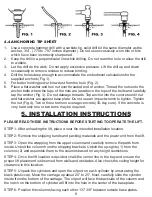
Page 11: ...the hole in the center of the base plate STEP 6 Position the columns facing each other 137 3 8 between outside base plates 4 4 ANCHORING TIP SHEET 1 Use a concrete hammer drill with a carbide tip soli...

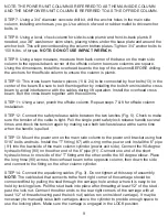
Page 12: ...12 Connect the safety release cable between the two latches Fig 5 Check to make sure the tension of the cable is tight Pull the single point safety lock release handle several times and check the tens...

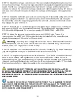
Page 13: ...in the power line just ahead of the power unit Size wire for 30 amp circuit Warning The wiring must comply with local code Have a certified electrician make the electrical hook up to the power unit P...

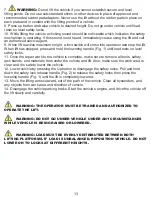
Page 14: ...IONS SUCH AS JERKY LIFT MOVEMENT OR DEFORMATION OF THE SUPERSTRUCTURE SUPPORT OR LOWER THE LIFT IMMEDIATELY CONTACT QUALIFIED SERVICE PERSONNEL WARNING PAY CLOSE ATTENTION WHEN SETTING THE LOCKS THE L...

Page 15: ...e the vehicle over the lift while keeping the vehicle parallel with the lift and aligning the center of gravity of the vehicle with the center of the lift NOTE The Center of Gravity COG of the vehicle...

Page 16: ...11 Once the repair work to the vehicle is complete make sure to remove all tools safety jack stands and materials from under the vehicle and lift Also make sure the work area is clear and it is safe t...

Page 17: ...worn or torn 5 Check hydraulic connections and hoses for leakage 6 Check chain connections Bends cracks and looseness 7 Check cable connections Bends cracks and looseness 8 Check for frayed cables in...

Page 18: ...e considered If operating in harsh dusty conditions shorter interval may be required The following items should only be performed by a trained maintenance expert Replace hydraulic hoses Replace chains...

Page 19: ...46 hydraulic oil or premium quality ATF DEXRON III MERCON 2 Visually check all hydraulic hoses and connections for tightness before each use to ensure proper working condition 3 Lightly oil the cylind...

Page 20: ...functioning correctly 3 Check that the safety lock is audibly and visibly operating correctly 4 Check the floor for stress cracks near the anchor bolts 7 2 4 LIFT STABILITY 1 Every six months check t...

Page 21: ...not run A Impeller fan cover is dented Take off and straighten B Faulty wiring Call electrician C Bad capacitor Call electrician D Low voltage Call electrician E Lift overloaded Reduce weight 5 Lift j...

Page 22: ...of energy sources per ANSI Z244 1 1982 before beginning any lift repairs Shall not modify the lift in any manner without prior written consent of the manufacturer Shall display this manual or copy sup...

Page 23: ...20 10 DIAGRAMS FIG 1 HD2P 11000ACX min 5 3 8 max 72...

Page 24: ...21 FIG 2 HD2P 11000ACX 17 3 8 14 3 16 6 3 8 18 7 8 20 1 2 2 9 17 1 4 137 3 8...

Page 25: ...3 HD2P 11000ACX Top Cable Sheave 3 8 Cable 3 4 Lock Nut Carriage Bottom Cable Sheave Safety Rack 2nd cable installation position for high column set up 1st cable installation position for low column...

Page 26: ...23 FIG 4 HD2P 11000ACX...

Page 27: ...24 FIG 5 HD2P 11000ACX...

Page 28: ...25 FIG 6 HD2P 11000ACX...

Page 29: ...ing washer 4 57 Hose clip 6 18 Flat washer 4 58 Plank parts B 1 19 Cover 2 59 Hook 2 20 Pulley 4 60 Sector board 1 21 Cover 2 61 Cover 1 22 Spindle 1 61 1 Cross screw 8 23 Cross screw 4 62 Bolt 6 24 O...

Page 30: ...2 Hydraulic cylinder 2 80 Hexangular bolt 4 93 Chain P 19 05 2 81 Flat washer 4 94 Spindle spring washer 4 82 Spring washer 4 95 Wheel spindle 2 83 Nut 4 96 Bronze spindle 4 84 Washer 2 97 Idler wheel...

Page 31: ...tent spindle 1 4 Check valve 1 5 Lowering valve 1 6 Bolt 1 7 Throttle valve 1 8 Escape oil valve 1 9 Oil box 1 10 Suction oil hose 1 11 Gear pump 1 12 Bumper valve 1 13 Valve seat 1 14 Motor 1 15 Powe...

Page 32: ...069 Greenwood IN 46142 1 888 908 4826 FAX 317 215 2770 www titanlifts com TITAN MARKETING LLC Copyright 2010 by Titan Marketing LLC All rights reserved No portion of this manual or any artwork contain...

Reviews: