background image

Using the ThinkRF R5750 Administration Console 


24 

ThinkRF R5750 Real Time Signal Analyzer User Guide 

Note

: Custom calibrated values may be over-written by a new firmware update. After 

restarting the unit once the firmware update is done, check on the 

Calibration

 link in the 

Administration Console to see which calibration file is specified at the top of the Filename 
list (for example, “System” or your customized file). 

To upload a custom calibration file: 

1. 

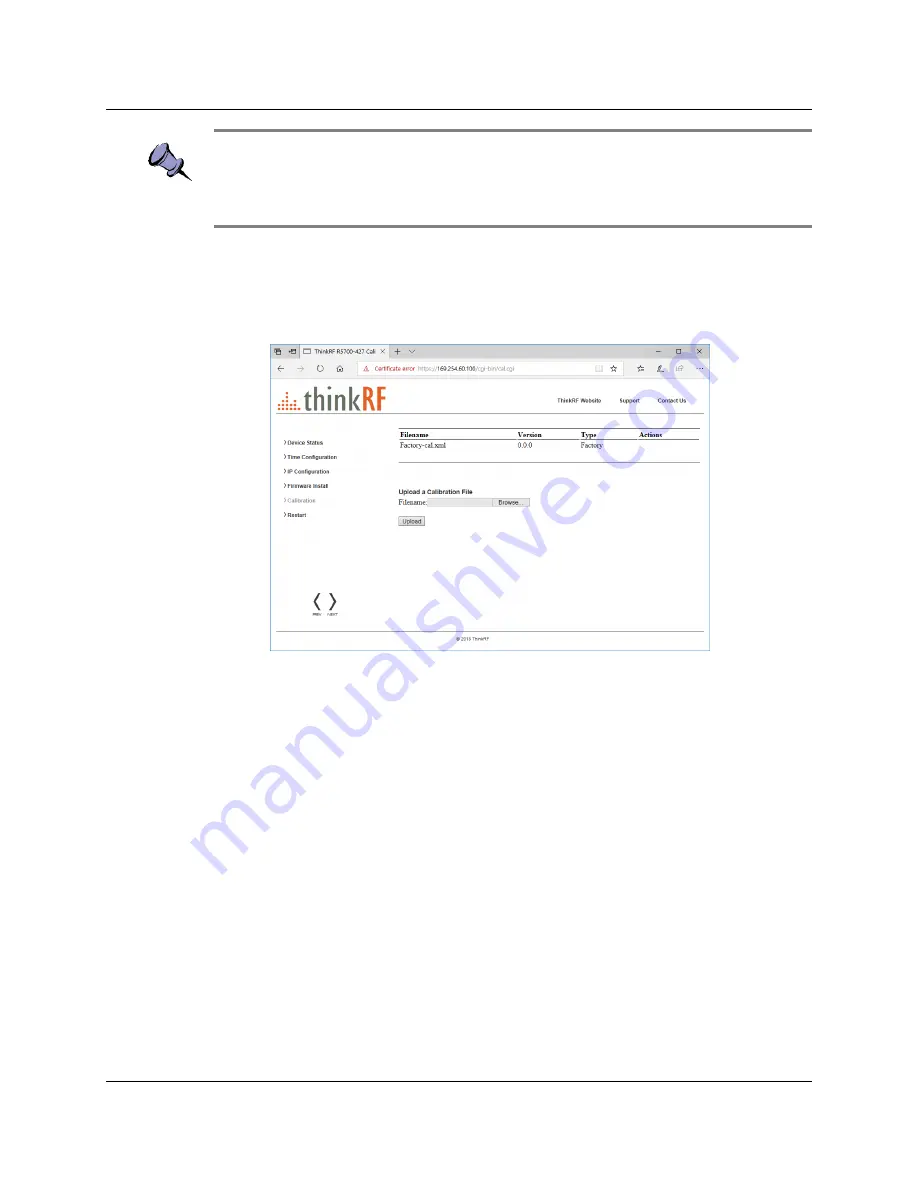
Click on the 

Calibration 

link in the left pane of the Administration Console.  

2. 

In the 

R5750 Device Calibration

 window (main pane), click 

Browse

 to open an 

Explorer window to navigate to the calibration setting file you want to upload. 


3. 

Click 

Upload

 to upload the file. 

When the upload is complete, the custom calibration file appears on the list of 
calibration files. The most recently uploaded file is listed at the top of the table. 

4. 

Restart the R5750 (you can click 

Restart

 in the left pane, or toggle the power 

switch). 
The boot-up may take longer than usual because the embedded system applies 
the new calibrated values. 

Summary of Contents for R5750

Page 1: ...eal Time Spectrum Analyzer with GNSS User Guide Version 1 0 March 2019 Document no 75 0040 190401 Copyright 2019 ThinkRF Corporation All rights reserved All product names are trademarks of their respe...

Page 2: ...RF s warranty policy all costs of repairs and shipping will be charged directly to the Customer ThinkRF will warrant repaired units for a period of 90 days from date of shipment from ThinkRF to the Cu...

Page 3: ...ng Your Network Topology and IP Address Allocation 14 Connecting Directly to the R5750 15 Connecting to the R5750 across a Network 17 Using the ThinkRF R5750 Administration Console 19 Viewing Device S...

Page 4: ...Clock Source LED 35 LOCK Indicator LED 35 LINK Status LED 36 ACT Indicator LED 36 Hardware Reference 37 System Specifications 37 SMA Connectors 37 Ethernet RJ 45 Port Pinout 38 GPIO Port Pinout 39 USB...

Page 5: ...lpful suggestions or references to additional information and material Caution This symbol means be careful In this situation you might do something that could result in equipment damage or loss of da...

Page 6: ...more information For all customers who hold a valid end user license ThinkRF provides technical assistance 9 AM to 5 PM Eastern Time Monday to Friday Contact us at support thinkrf com or by calling 1...

Page 7: ...nology that provides industry leading combined sensitivity tuning range instantaneous bandwidth and scan rate Additionally the R5750 provides real time sophisticated triggering search and loss less ca...

Page 8: ...Transport VRT protocol for digitized data and its associated context information APIs are provided for interfacing and performing data acquisition and spectral analysis with Python C C MATLAB and Lab...

Page 9: ...the R5750 contains the power input 10 MHz reference clock I O hardware reset button input connector for the GNSS antenna USB console CNSL port Ethernet port and GPIO port Underside The underside of th...

Page 10: ...Overview of the ThinkRF R5750 10 ThinkRF R5750 Real Time Signal Analyzer User Guide...

Page 11: ...ESD occurs when electronic components are improperly handled and is one of the major causes of device failures in the semiconductor industry Electrostatic discharge is more likely to occur with the co...

Page 12: ...connect the receiver and GNSS antennae the Ethernet cable and the power cable 1 Screw the antenna on to the R5750 RF IN antenna input SMA connector on the device s front panel Carefully turn the ante...

Page 13: ...the unit on Note See the Using the ThinkRF R5750 Administration Console section for a description of the R5750 status Choosing the Mount Location for the R5750 After you have connected the R5750 rece...

Page 14: ...termining Your Network Topology and IP Address Allocation To connect with the R5750 analyzer you must decide the topology of your network connection and how your R5750 obtains its IP address Network T...

Page 15: ...llocation from one supported method to another For instructions on configuring a static IP address via the Administration Console see the Configuring the R5750 IP Address section If your R5750 is conf...

Page 16: ...akes approximately one minute or longer Note While the R5750 is searching for a DHCP server the STS LED blinks yellow slowly until it obtains an IP address either via DHCP or Auto IP The STS LED blink...

Page 17: ...need to use the same IP address allocation method but if you are using the ThinkRF Discovery tool to locate the R5750 analyzer they must be on the same subnet If you are using dynamic IP address alloc...

Page 18: ...If you are using static IP and the Discovery tool cannot locate the R5750 you need to have prior knowledge of its static IP address or use the USB console If necessary consult your network administra...

Page 19: ...pgrade the R5750 software and firmware upload customized calibration settings restart the R5750 All of these functions may be performed over the network either locally or remotely You can connect to t...

Page 20: ...ones Conversely the web dialog translates and displays the R5750 time based on the local time zone setting of the PC To configure the R5750 time synchronization method 1 Click on the Time Configuratio...

Page 21: ...nicate with the R5750 is via that IP address If you mistakenly enter the wrong IP address and or subnet mask or forget the IP address you can change the IP configuration using the USB console or by re...

Page 22: ...e at https www thinkrf com firmware updates Note Updating the R5750 firmware may over write any user defined calibrated values See the Customizing R5750 Calibration Settings section for more informati...

Page 23: ...re are new changes to the calibration setup or Auto IP connection method is used Customizing R5750 Calibration Settings The R5750 supports user defined calibration settings if you do not want to use t...

Page 24: ...alibration file 1 Click on the Calibration link in the left pane of the Administration Console 2 In the R5750 Device Calibration window main pane click Browse to open an Explorer window to navigate to...

Page 25: ...bration settings to system defaults at any time by deleting all custom calibration files from the system You cannot delete the system calibration file To restore the default calibration settings 1 Cli...

Page 26: ...k on the Restart link in the left pane of the Administration Console 2 In the R5750 Device Restart window main pane click Restart Depending on your network settings the R5750 may obtain a different IP...

Page 27: ...p 2 Connect The USB cable to the R5750 USB console port and your PC s USB port Your PC should automatically detect the R5750 as a new USB device and install the appropriate driver 3 Open the Windows C...

Page 28: ...e cursor does not appear the USB to UART Bridge may be expecting a typical VT100 terminal response Press Ctrl C and Enter until the cursor appears The cursor may take several seconds to appear 6 Enter...

Page 29: ...sk or forget the IP address you can change the IP configuration using the USB console or by restarting the R5750 To configure the R5750 IP address via the USB console 1 Open a connection to the R5750...

Page 30: ...ctions You can also configure GNSS settings via various APIs such as C API Python etc Note GNSS timestamp information is recorded in the GNSS VRT packets which are returned approximately every 1 secon...

Page 31: ...location Data You can obtain real time GNSS position data from the R5750 GNSS module During data capture the real time GNSS location context packets are sent periodically in the VRT data stream It is...

Page 32: ...command STATus QUEStionable CONDition This command queries the Questionable Status Register QSR and returns the decimal equivalent of a binary value When 0 is returned the GNSS data is current When 51...

Page 33: ...these steps to reset your R5750 analyzer 1 If not already powered on power on the R5750 2 When the R5750 is powered on press and hold the Reset button on the rear panel of the device for at least 5 s...

Page 34: ...ge in sequence from left to right until the firmware is initialized The sequence may occasionally stop briefly during the boot up phase PWR Indicator LED Internal Power Status Off Not receiving power...

Page 35: ...erence Clock Source Solid green Internal clock reference selected and PLL has successfully locked to it Slow blink green External clock reference or GNSS clock reference selected and PLL has successfu...

Page 36: ...LINK Status LED Ethernet Link Status Off No Ethernet link connection Orange 10 100 Mbit Ethernet link connection Green GigE Ethernet link connection ACT Indicator LED The ACT indicator LED indicates w...

Page 37: ...IN 10 MHz REF IN and OUT1 GPS Input supply voltage 12 VDC 5 Input supply current 1 8 A maximum Operating temperature 32 to 122 F 0 to 50 C 1 Availability depends on the product model or application C...

Page 38: ...s Guide it is best to inject signals lower than 10 dBm Additionally any external signal sources connected to RF IN must be turned on only after powering on the R5750 and turned off prior to powering...

Page 39: ...amage to the R5750 Do not use the GPIO without prior consultation with ThinkRF s service organization The following pinouts are specific to the R5750 models only Pin Direction Voltage Signal 1 2 5 8 1...

Page 40: ...ware Reference 40 ThinkRF R5750 Real Time Signal Analyzer User Guide USB Console Port Pinout Pin Signal 1 5 VDC 2 Data 3 Data 4 Ground RJ 45 Straight Through Ethernet Cable RJ 45 Crossover Ethernet Ca...

Page 41: ...een 20 C to 25 C Caution Do not expose the device to direct sunlight or radiation from other sources of heat Some regular maintenance is needed to maintain the unit in its good working state This incl...

Reviews: