Thermo Fisher Scientific CryoExtra CE8100 Series
Preventative Maintenance | 63
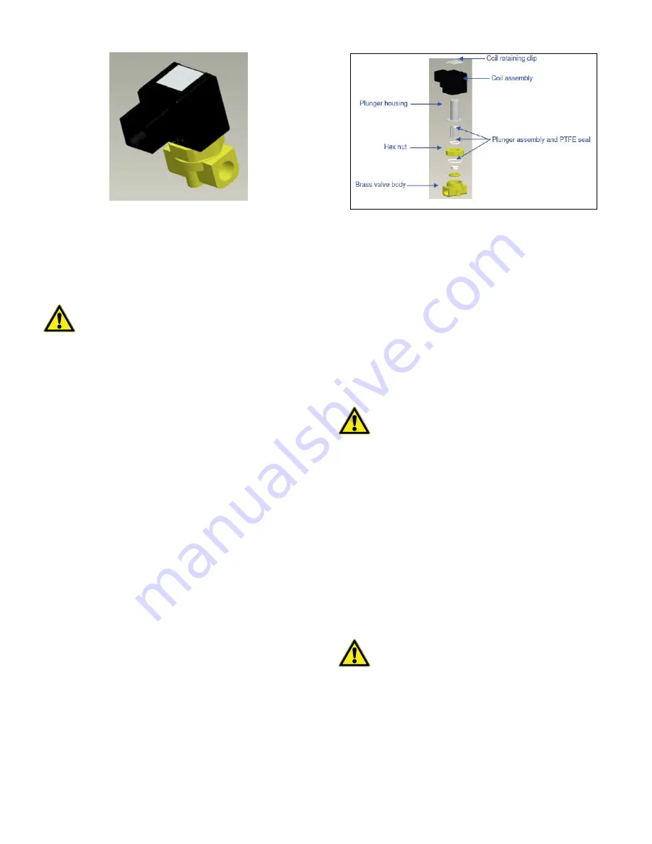
Figure 17. SMC Solenoid Valve (Current
Production)
SMC (black) Solenoid Valve Replacement
1. Remove plumbing shroud to gain access to plumbing
system.
2. Remove coil retaining clip by inserting a flathead
screwdriver between the clip and the edge of the coil
body. Twist the screwdriver and the clip should slide off.
3. Remove and discard the coil assembly.
4. Using a crescent wrench loosen hex nut and remove the
plunger housing. Remove plunger housing and plunger
assembly. Discard these parts.
5. Remove any debris that may have collected in brass
valve body.
6. Inspect the brass valve body of the solenoid valve for
nicks or damage. If the sealing surface appears to be in
good condition, the valve body may be reused. If the
sealing surface is damaged, the plumbing will need to be
disassembled and the entire body will need to be
replaced (this is not common).
7. Disassemble a new SMC valve (PN 14224611S) using
the above procedure.
8. Install the new plunger, plunger housing and coil
assembly onto the old valve body.
9. Assembly valve with new components in the reverse
order.
10. Verify that no leaks are present using leak detect solution.
11. Open the LN
2
supply valve and initiate a fill cycle by
pressing “Fill Start’. Allow the fill cycle to complete and
verify that flow stops at the termination of the fill cycle.
Note:
If the brass valve body requires replacing, the freezer
plumbing will need to be disassembled and the entire valve
replaced (PN 14224611S). It is typically easier to start
disassembling the plumbing assembly beginning at the fill tee
for fill valve replacement or the gas bypass muffler for gas
bypass valve replacement.
Note:
When installing a complete new valve, ensure it is
oriented correctly. An “N” is engraved on the side of the SMC
brass valve body. The valve should be installed so that this “N”
is on the inlet side of the valve.
Relief Valve Replacement
1. Remove plumbing shroud to gain access to plumbing
system.
2. If equipped with a relief valve deflector, loosen the
deflector clamp and slide off the deflector.
3. Loosen the relief valve and remove it from the plumbing
assembly. Be sure to support the attachment tube with
wrench to prevent damage from twisting.
4. Install new relief valve (PN 1810032) applying new. Teflon
tape if needed. Ensure relief valve is rated to 50 PSI (3.4
bar).
CAUTION :
Ensure that the LN
2
supply valve is
closed and the plumbing assembly is vented
before removing the solenoid valves.
CAUTION :
Ensure that the LN
2
supply valve is
closed and the plumbing assembly is vented
before removing the relief valve.
CAUTION :
Installing a relief valve with a different
pressure rating could prevent proper operation
and lead to a dangerous over pressurized
condition.


