44
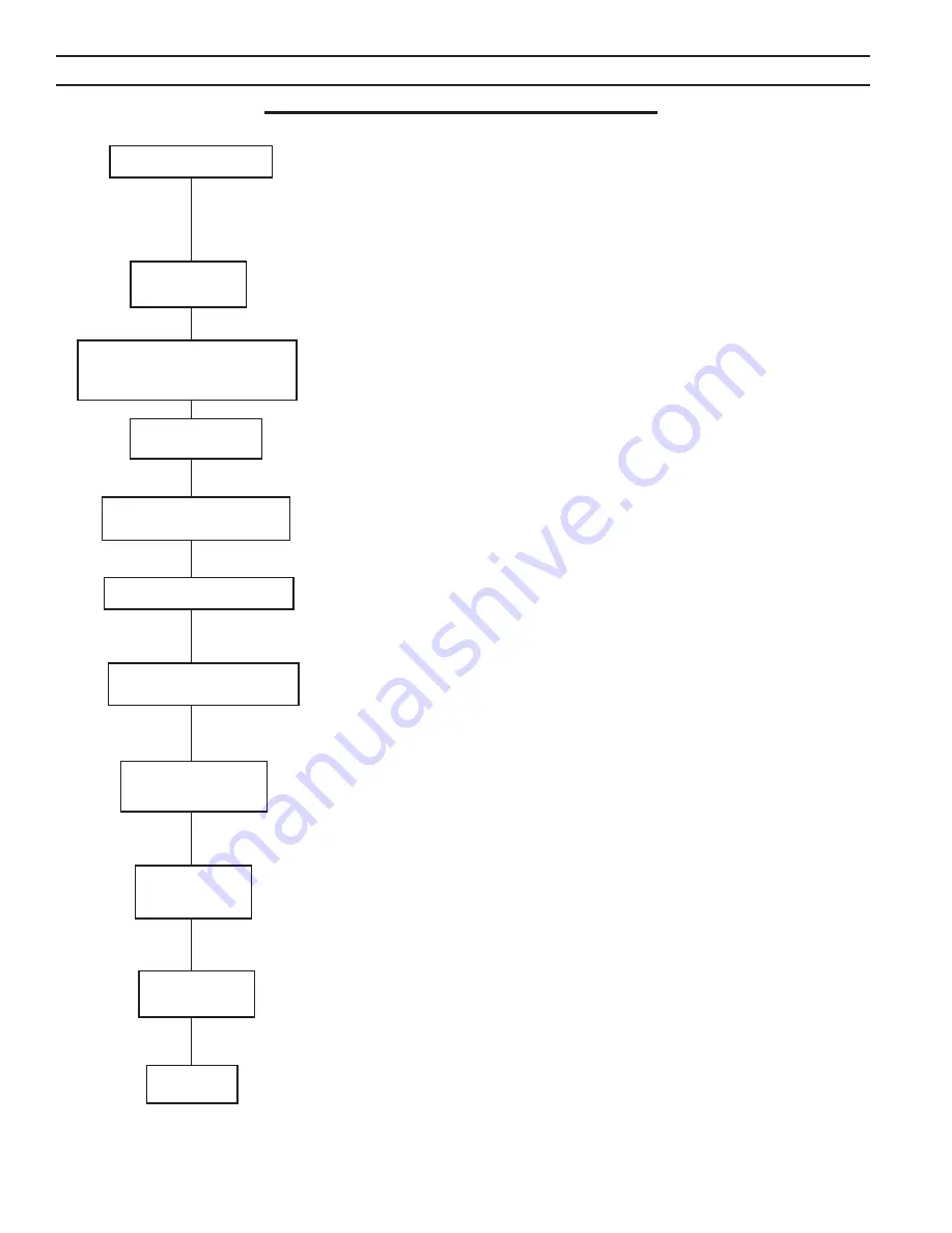
NORMAL SEQUENCE OF OPERATION
Limits and operating controls such as safety and operating temperature limits,
water flow switch, thermal fuse switches and high/low gas pressure switch
contacts must be closed to initiate and continue burner sequence. Flame
signal must not be present. Airflow switch must be open.
Control terminal 5 is energized and all safety and operating control contacts
are closed. Control terminal 4 is energized to start the combustion air fan.
Contacts close when fan generates enough differential air pressure to actuate
combustion air flow switch diaphragm.
Fan purges combustion chamber and venting for 30 seconds.
Pilot gas valve(s) and ignition transformer are energized. Pilot gas flows to
pilot burner and is ignited.
Ignition transformer is de-energized after 5 seconds. Presence of pilot flame
is detected by ultraviolet scanner. Flame signal exceeds 1.5 volts DC.
Main gas valves are energized. Gas flows to main burner and is ignited by
pilot flame. Pilot and main flames are detected by ultraviolet scanner. Flame
signal continues to maintain 1.5 to 5.0 volts DC.
After 5 seconds, pilot gas valve(s) is de-energized. Gas flow to pilot stops.
Pilot flame is extinguished. Main flame is detected by ultraviolet scanner.
Flame signal continues to maintain 1.5 to 5.0 volts DC.
Main burner continues to operate until call for heat ends, contacts of a safety
or operating control open, electrical power is interrupted, or the flame signal
drops below 1.5 volts DC. Modulating boilers operate based on the load,
determined by the difference between the bulk boiler water temperature and
the boiler water set point.
Main gas valves are de-energized. Gas flow to main burner stops. Main
flame is extinguished. Fan continues to operate for 60 seconds to EVOcuate
combustion chamber and venting.
Boiler in Standby
Call for Heat
Combustion Air Flow Switch
Contacts Make
Pilot Flame Establishing
Period Begins
Early Spark Termination
Main Flame Establishing
Period Begins
Run Period Begins
Run Period
Post Purge
Standby
30 sec.
5 sec.
5 sec.
3 sec.
Prepurge Begins
After 60 seconds fan stops.
VI. Boiler Operational Sequence
Summary of Contents for EVO-1000
Page 13: ...13 Figure 4 Vertical Pressurized Venting...
Page 15: ...15 Figure 5 Typical Negative Pressure Conventional Venting...
Page 17: ...17 Figure 7 Vertical Air Intake Piping...
Page 26: ...26 Figure 9a Standard UL FM CSD 1 Wiring Diagram on off EVO 500 2000...
Page 27: ...27 Figure 9b Standard UL FM CSD 1 Wiring Diagram Modulation EVO 500 2000...
Page 30: ...30 Figure 11 Modular System Horizontal Air Intake Piping...
Page 31: ...31 Figure 12 Modular System Vertical Air Intake Piping...
Page 32: ...32 Figure 13 Modular System Typical One Pipe Water Piping...
Page 33: ...33 Figure 14 Modular System Typical Primary Secondary Water Piping...
Page 34: ...34 Figure 15 Modular System Typical Primary Secondary without System Pump...
Page 35: ...35 Figure 16 Modular System Typical Reverse Return Water Piping...
Page 36: ...36 Figure 17 Modular System Reverse Return with System Pump Only...
Page 37: ...37 Figure 18 Modular System Typical Primary Secondary with Reverse Return...
Page 47: ...47 This Page Intentionally Left Blank...
Page 48: ...48 Troubleshooting Guide B Troubleshooting Guide...
Page 49: ...49 Troubleshooting Guide...
Page 53: ...53 This Page Intentionally Left Blank...
Page 54: ...54 Figure 19 Combustion Chamber Assembly...
Page 56: ...56 Figure 20 Burner Assembly FRONT VIEW TOP VIEW...
Page 58: ...58 Figure 21 UL FM CSD 1 Main Gas Train Assembly...
Page 60: ...60 Figure 22a DB B DB B w POC Gas Train 500 750 Figure 22b DB B DB B w POC Gas Train 1000 2000...
Page 62: ...62 Figure 23 Jacket Panels 4D 4J 4C 4B 4F 4I 4G 4E 4R 4K 4H 4J 4N 4M 4L 4Q 4A 4P 4P...
Page 64: ...64 Figure 24a Control Panel Assembly On Off...
Page 66: ...66 Figure 24b Control Panel Assembly Modulation...
Page 68: ...68 Figure 25 Bishop Pilot Assembly...
Page 72: ...72 NOTES...
Page 73: ...73 NOTES...
Page 74: ...74 NOTES...
Page 75: ...75 NOTES...


