V2.1
–
TH3D EZABL
™
Pro Installation Guide -
Copyright © 2021 TH3D Studio LLC
–
ALL RIGHTS RESERVED
3
Getting Started
Welcome to the EZABL
™
Pro kit installation guide!
This will walk through the steps to install the EZABL
™
Pro sensor on the printer. Be sure to
follow all the steps and if you have issues or a question do not hesitate to reach out to us by
visiting
http://ContactUs.TH3DStudio.com
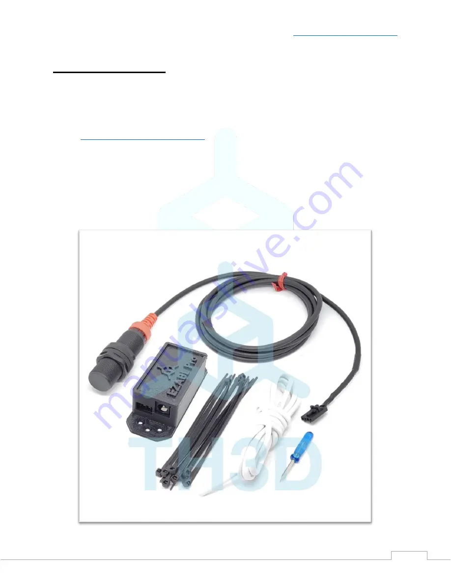
There are optional accessories for the EZABL
™
Pro Kit like AC power adapter or USB power
adapter that are not pictured below. If you ordered these options, they will be in the EZABL
™
Pro kit package when you receive it.
We are always making things better so the case or sensor may look slightly different than the
below pictures.