GB-10
RANSOMES G PLEX II Series :WD
MAINTENANCE AND PARTS MANUAL
GB
WARNING
•
This procedure MUST be performed as
specified and only by properly trained
service personnel.
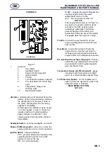
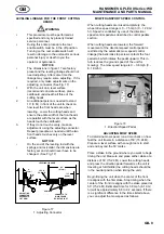
Adjusting the speed control screw out (increasing
length) will reduce the mow speed. Adjusting the
speed control screw in (shortening length) will
increase mow speed.
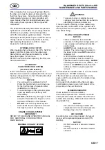
Determine which direction to adjust the mow speed
screw. Loosen the locking nut and adjust speed
control screw, snug up the locking nut and run the
time test again, repeat as necessary. When correct
mow speed has been obtained, tighten the locking
nut (See Fig. 19).
2
1
Figure 19
1. Mow Speed Adjustment Screw
2. Locking Nut
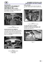
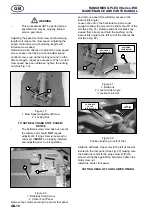
TO SET BELLCRANK STOP SCREW:
NOTICE
•
The bellcrank stop screw has been set at
the factory and should
NOT
require
adjustment. If stop screw is loosened or
removed, it
MUST
be properly installed
and adjusted prior to unit operation.
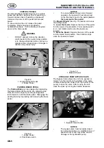
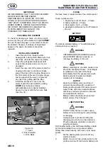
1
2
Figure 20
1. Bellcrank Stop Screw
2. Center Foot Panel
Remove the screws securing the center foot panel
and remove panel (this will allow access to the
lockout link angle).
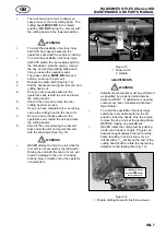
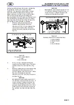
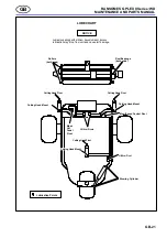
Loosen the nut on the bellcrank stop screw just
enough to allow the screw to be slid to the left of the
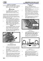
slot (See Fig. 21). Rotate bellcrank clockwise (as
viewed from above) and hold the bushing on the
lockout link angle to the left end of the lockout link
slot (See Fig. 22).
2
1
AS VIEWED
FROM BELOW
BELLCRANK
STOP SCREW
3
Figure 21
1. Bellcrank
2. Lockout Link Angle
3. Lockout Link slot
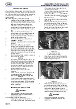
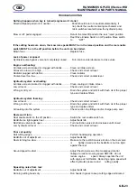
POSITIONED
TO THE
LEFT OF SLOT
LOCK
OUT LINK
Figure 22
Position Bushing to Left of Slot
Slide the bellcrank stop screw to the left of the slot
located in the foot panel (See Fig. 20) making sure
the bellcrank contacts the stop screw. With the
screw held tightly against the bellcrank, tighten the
stop screw nut.
Install the center foot panel.
CUTTING HEAD LIFT AND LOWER TIMING
Summary of Contents for D722B
Page 2: ...2000 Textron Inc All Rights Reserved...
Page 24: ...GB 22 RANSOMES G PLEX II Series WD MAINTENANCE AND PARTS MANUAL GB...
Page 27: ...F 25 RANSOMES G PLEX II S rie WD NOMENCLATURE ET MAINTENANCE F...
Page 49: ...F 47 RANSOMES G PLEX II S rie WD NOMENCLATURE ET MAINTENANCE F...
Page 51: ...NL 49 RANSOMES G PLEX II Serie WD ONDERHOUDSHANDLEIDING EN ONDERDELENLIJST NL...
Page 71: ...NL 69 RANSOMES G PLEX II Serie WD ONDERHOUDSHANDLEIDING EN ONDERDELENLIJST NL...
Page 73: ......
Page 75: ...D 73 RANSOMES G PLEX II Serie WD WARTUNGS UND ERSATZTEILHANDBUCH D...
Page 95: ...D 93 RANSOMES G PLEX II Serie WD WARTUNGS UND ERSATZTEILHANDBUCH D...
Page 97: ...D 95 RANSOMES G PLEX II Serie WD WARTUNGS UND ERSATZTEILHANDBUCH D...
Page 99: ...I 97 RANSOMES G PLEX II Serie WD MANUALE DELLA MANUTENZIONE E DELLE PARTI DI RICAMBIO I...
Page 119: ...I 117 RANSOMES G PLEX II Serie WD MANUALE DELLA MANUTENZIONE E DELLE PARTI DI RICAMBIO I...
Page 132: ...Parts 12 RANSOMES G PLEX II Series WD MAINTENANCE AND PARTS MANUAL 5b HYDRAULIC TANK FITTINGS...
Page 168: ...Parts 48 RANSOMES G PLEX II Series WD MAINTENANCE AND PARTS MANUAL 20 DECALS...
Page 184: ...Parts 64 RANSOMES G PLEX II Series WD MAINTENANCE AND PARTS MANUAL 25 REEL ASSEMBLY 1...
Page 186: ...Parts 66 RANSOMES G PLEX II Series WD MAINTENANCE AND PARTS MANUAL 26 REEL ASSEMBLY 2...
Page 188: ...Parts 68 RANSOMES G PLEX II Series WD MAINTENANCE AND PARTS MANUAL 27 REAR ROLLER...
Page 190: ...Parts 70 RANSOMES G PLEX II Series WD MAINTENANCE AND PARTS MANUAL 28 REAR ROLLER...
Page 214: ......
Page 215: ......


