DYNAMIC POWER PATH MODE
Charging current is reduced to supply
the load to SW/OUT and LSLDO
Battery Termination is disabled
2X TIMER MODE
VINDPM MODE
Charge current is reduced , 2X TIMER
mode is active (if enabled ) and
termination is disabled
BAT SUPPLEMENT MODE
BAT supplements the load at
SW/OUT and LSLDO
½ CHARGE MODE
Charging current is reduced to half the
programmed or default current
VBATREG
±
140mV MODE
VBATREG is reduced by 140mV from
the programmed or default VBATREG
DEFAULT MODE CHARGE
No HOST or I2C is not available, ILIM,
ISET, and ITERM have resistors
populated .
Default OTP charge settings are used if
no resistors are populated
Register settings used if changed in
I2C
VALID CHARGE INPUTS
RESET
PRE-CHARGE MODE
Charge current is reduced
to the Pre-charge current
level to slowly bring up the
VBAT voltage
ILIM
VINDPM
TS_FAULT
PRE_CHARGE
VBAT<V
BATUVLO
VBAT>V
BATUVLO
+ 150 mV
CC MODE
CV MODE
VIN
”
VIN_DPM
VIN>VIN_DPM
ICHRG+ISW+ILDO>ILIM
ICHG
”
0
PMID<VBAT-V
BSUP1
ICHG>0
PMID<VBAT-V
BSUP2
ICHRG+ISW+ILDO<ILIM
TS_FAULT (COOL)
TS_FAULT (WARM)
!TS_FAULT
!TS_FAULT
Comments about naming convention:
^
/
^
}Œ
^
HZ_
DK
^
-> Register name: event caused by user / configuration
^
!
^
-> Not
^
y
^
-> Event caused by external influence
^
Event|
condition
^
-> describes the event with a specific condition
BAT-SHORT MODE
Charge current is reduced to
the Bat-Short current level to
slowly bring up the VBAT
voltage
VBAT<V
BATSHORT
VBAT>V
BATSHORT
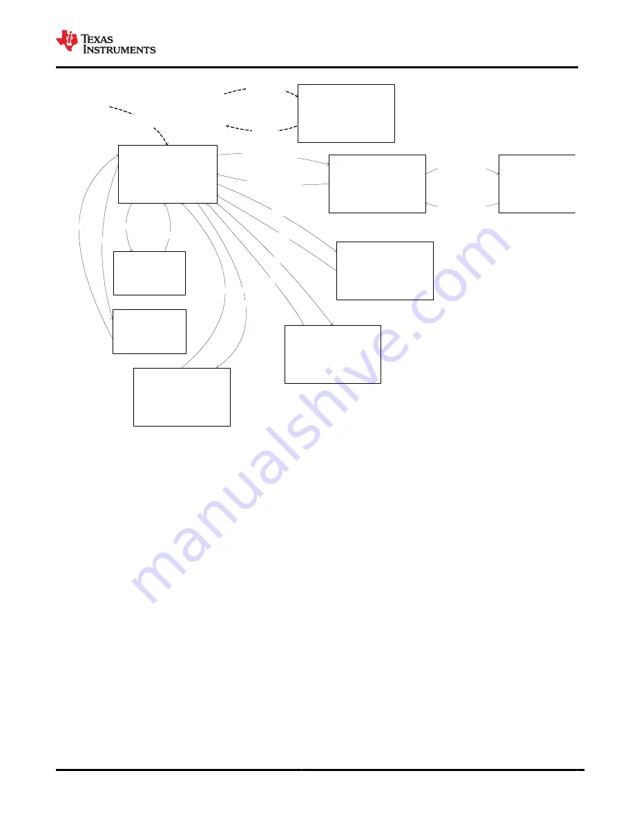
Figure 9-6. Change State Diagram
9.5 Programming
9.5.1 Serial Interface Description
The device uses an I
2
C compatible interface to program and read many parameters. I
2
C is a 2-wire serial
interface developed by NXP. The bus consists of a data line (SDA) and a clock line (SCL) with pull-up structures.
When the bus is idle, both SDA and SCL lines are pulled high. All the I
2
C compatible devices connect to the I
2
C
bus through open drain I/O terminals, SDA and SCL. A master device, usually a microcontroller or digital signal
processor, controls the bus. The master is responsible for generating the SCL signal and device addresses. The
master also generates specific conditions that indicate the START and STOP of data transfer. A slave device
receives and/or transmits data on the bus under control of the master device.
The device works as a slave and supports the following data transfer modes, as defined in the I
2
C BUS
Specification: standard mode (100 kbps) and fast mode (400 kbps). The interface adds flexibility to the
battery management solution, enabling most functions to be programmed to new values depending on the
instantaneous application requirements. The I
2
C circuitry is powered from the battery in active battery mode. The
battery voltage must stay above V
(BATUVLO)
when no V
IN
is present to maintain proper operation. The host must
also wait for SYS to come up before starting communication with the part.
The data transfer protocol for standard and fast modes is exactly the same; therefore, they are referred to as
the F/S-mode in this document. The device only supports 7-bit addressing. The device 7-bit address is 6A (8-bit
shifted address is D4).
SLUSCZ6A – JANUARY 2018 – REVISED MAY 2021
Copyright © 2021 Texas Instruments Incorporated
31
Product Folder Links:


