2. Hardware Overview
Component Identification
6
2.1 Component Identification
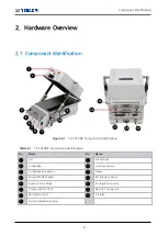
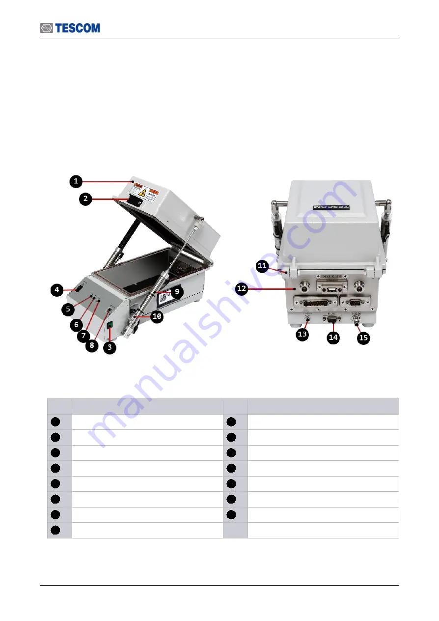
Figure 2-1
TC-5910DP Component Identification
Table 2-1
TC-5910DP Component Identification
No.
Name
No.
Name
1
Lid
9
Air Cylinder
2
Lid Handle
10
Lid Close Sensor
3
Lid Open/Close Button
11
Hinge
4
Power ON/OFF Switch
12
I/O Interface Panel
5
Green LED for PASS
13
DC Input Connector
6
Orange LED for TEST
14
RS-232C Connector
7
Red LED for FAIL
15
Air Inlet
8
Fixture Operation Button
Summary of Contents for TC-5910DP
Page 1: ...TC 5910DP Pneumatic Shield Box User Manual R20191023...
Page 9: ...PART 1 1 Getting Started...
Page 13: ...PART 2 5 Hardware Description...
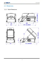
Page 17: ...Dimensions 9 2 2 Dimensions 2 2 1 Outer Dimensions...
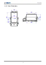
Page 18: ...10 Dimensions 2 2 2 Inner Dimensions...
Page 23: ...PART 3 15 Putting into Operation...
Page 49: ...PART 4 41 Maintenance...
Page 57: ...Expendables and Accessories 49 Figure 7 1 TC 5910DP Expendables Location...


