Revision A
November 25, 1996
2-9
2.5
ANTENNA INSTALLATION
A 50 broad-band VHF communication antenna covering the range of 118.00 to 136.975
MHz is recommended. Whips or bent antennas do not provide the best performance if the
radio is to be used over its entire range of 118.00 to 136.975 MHz. Connect the antenna to
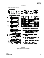
the Terra by Trimble TX 760D using standard 50 ohm coaxial antenna cable such as RG
58A/U. Terminate the cable with BNC coaxial cable connectors as required. Insure tested
speed of the antenna matches top speed of the aircraft. Minimum ground plane size is
recommended to be a 42" diameter circle around antenna mounting point to prevent loss of
transmit range.
CAUTION!
Proper installation of the coaxial cable and the antenna per FAA Aircraft
Inspection and Repair Document AC 43.13-2A, Chapter 3, is very important
to prevent possible mismatch of the transmitter output. Use an ohm meter to
verify no short curcuits exist between the center conductor and shield
conductor or other wiring.
2.6
OPERATIONAL CHECK-OUT
1.
Rotate volume control (small inner left hand knob) clockwise to turn transceiver on.
2.
Rotate “Tune” (right hand) knob to obtain desired frequency in right-hand window.
Verify that the faster the knob is rotated, the more the frequency changes with each
detent.
3.
Press the “<—>” (TRANSFER) button and verify that the two frequencies “swap”
sides in the display.
4.
Adjust squelch control (large outer left hand knob) until the switch clicks into a fully
counterclockwise position. This is the automatic squelch mode. No background
noise should be heard. If there is a received signal it should be heard. Rotating the
squelch control in a clockwise direction activates the manual squelch mode. Rotate
the control clockwise until background noise is heard. Adjust volume control for
desired level during receipt of transmissions. Then rotate squelch control slightly
counterclockwise until the noise ceases.
5.
Plug microphone into remote microphone jack.
6.
Verify proper transmitter operation by communicating with another station. Verify
at the low, medium, and high frequencies if possible.
7.
Plug headset into remote jack and observe the quality of audio output. If transmit
sidetone is used, verify quality and level in headset.
Summary of Contents for TX 760D
Page 24: ...3 2 Revision A November 25 1996 THIS PAGE INTENTIONALLY LEFT BLANK ...
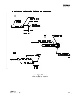
Page 25: ...Revision B December 16 1996 3 3 Figure 3 2 Coax Connector Drawing ...
Page 26: ...3 4 Revision A November 25 1996 THIS PAGE INTENTIONALLY LEFT BLANK ...
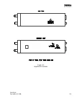
Page 27: ...Revision A November 25 1996 3 5 Figure 3 3 Adjustment Locations ...
Page 28: ...3 6 Revision A November 25 1996 THIS PAGE INTENTIONALLY LEFT BLANK ...
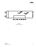
Page 29: ...Revision A November 25 1996 3 7 Figure 3 4 VOX Jumper Locations ...
Page 30: ...3 8 Revision A November 25 1996 THIS PAGE INTENTIONALLY LEFT BLANK ...
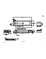
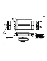
Page 31: ...Revision A November 25 1996 Figure 3 5 Sheet 1 of 2 Outline Dimensions 3 9 10 ...
Page 32: ...Revision A November 25 1996 Figure 3 5 Sheet 2 of 2 Outline Dimensions 3 11 12 ...
Page 33: ...Revision A November 25 1996 Figure 3 6 Interconnect Diagram 3 13 14 ...
Page 39: ...4 6 Revision A November 25 1996 Figure 4 1 Front Panel Controls ...
Page 41: ...5 2 Revision A November 25 1996 THIS PAGE INTENTIONALLY LEFT BLANK ...
Page 43: ...6 2 Revision A November 25 1996 6 2 INSTALLATION NOTES ...

