2-10
Revision A
November 25, 1996
2.7
FINAL INSPECTION
1.
Insure that all wiring is properly routed and secure. Dress harnessing neatly and
secure in place with cable ties.
NOTE:
It is recommended that the TX 760D be installed and locked into the
mounting sleeve before tying and securing the wiring harness. This will
ensure proper alignment of the “floating” connectors to facilitate removal
and replacement of the TX 760D.
Check connector integrity and locking devices. Insure locking devices are
functioning properly and are secured. Verify cabling is not “clotheslined”
and provisions have been made for service loops. Pull yoke to its maximum
travel. While slowly returning yoke to its normal position, rotate yoke left
and right to insure all cabling is routed and tied up properly. Cycle rudder
pedals and verify that they are free and cables are unobstructed. Install gust
locks, perform complete check-out of all avionics including dimmers. Secure
aircraft power and all master switches.
2.
Have installation inspected by someone authorized under Federal Aviation
Regulation Part 65.
3.
Add the Terra by Trimble TX 760D to the aircraft equipment list, including serial
number. Complete FAA Form 337 if required, and make required airframe logbook
entries. A weight and balance change may be required, depending on the type of
aircraft.
4.
Complete FCC License Applications as required and file them. The Type
Acceptance Number for the application is CCXTX760D.
5.
Complete warranty card and return to Trimble.
Summary of Contents for TX 760D
Page 24: ...3 2 Revision A November 25 1996 THIS PAGE INTENTIONALLY LEFT BLANK ...
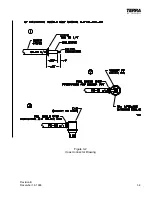
Page 25: ...Revision B December 16 1996 3 3 Figure 3 2 Coax Connector Drawing ...
Page 26: ...3 4 Revision A November 25 1996 THIS PAGE INTENTIONALLY LEFT BLANK ...
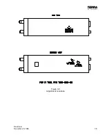
Page 27: ...Revision A November 25 1996 3 5 Figure 3 3 Adjustment Locations ...
Page 28: ...3 6 Revision A November 25 1996 THIS PAGE INTENTIONALLY LEFT BLANK ...
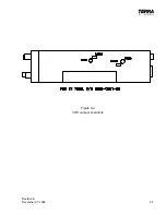
Page 29: ...Revision A November 25 1996 3 7 Figure 3 4 VOX Jumper Locations ...
Page 30: ...3 8 Revision A November 25 1996 THIS PAGE INTENTIONALLY LEFT BLANK ...
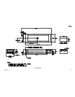
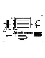
Page 31: ...Revision A November 25 1996 Figure 3 5 Sheet 1 of 2 Outline Dimensions 3 9 10 ...
Page 32: ...Revision A November 25 1996 Figure 3 5 Sheet 2 of 2 Outline Dimensions 3 11 12 ...
Page 33: ...Revision A November 25 1996 Figure 3 6 Interconnect Diagram 3 13 14 ...
Page 39: ...4 6 Revision A November 25 1996 Figure 4 1 Front Panel Controls ...
Page 41: ...5 2 Revision A November 25 1996 THIS PAGE INTENTIONALLY LEFT BLANK ...
Page 43: ...6 2 Revision A November 25 1996 6 2 INSTALLATION NOTES ...

