1-2
Revision A
November 25, 1996
The following are pertinent specifications for the FCC type-accepted Terra by Trimble Model
TX 760D transceiver.
1.3.1
MECHANICAL SPECIFICATIONS
Mounting:
Panel mounted using mounting tray supplied with unit
Overall Dimensions:
13.05" long, 3.125" wide, 1.625" high (33.14 cm long, 7.9375
cm wide, 4.1275 cm high)
Mounting Dimensions:
11.45" behind panel,
3.125" wide, 1.625" high (29.08 cm behind panel, 7.9375 cm
wide, 4.1275 cm high)
Panel Cutout:
3.03" x 1.54" (7.692 cm x 3.9116 cm)
Weight:
1.50 pounds (0.680 kg)
Connectors:
Antenna input/output; BNC Interconnect; 15 pin “D” type
1.3.2
POWER REQUIREMENTS
The Terra by Trimble TX 760D transceiver requires 13.75 VDC +10%, -20% input at
2.5 amps maximum load condition.
1.3.3
ENVIRONMENTAL SPECIFICATIONS
Maximum Operating Conditions
Altitude:
To 30,000 feet (9,150 meters)
Humidity:
To 95% at 50 C (122 F)
Temperature
Range:
-20 C (-4 F) to +55 C (+131 F)
Vibration:
0.5 G from 5 to 500 Hz
1.3.4
ELECTRICAL SPECIFICATIONS
(All specifications at 13.75 VDC nominal)
RECEIVER
Frequency Range:
118.00 to 136.975 MHz
Number of Channels:
760
Channel Spacing:
25 KHz
Sensitivity:
Less than 2
µ
V for 6dBm signal plus noise to noise ratio.
Selectivity:
Typically -6dBm at 14 KHz and -60 dBm at 40 KHz.
Squelch Sensitivity:
Automatic: 2 to 5
µ
V
Manual:
25 to 150
µ
V
Automatic Gain
Control (AGC):
Audio flat within 3dB for 3
µ
V to 30,000
µ
V input.
Undesired Response:
Greater than 60dBm down.
Summary of Contents for TX 760D
Page 24: ...3 2 Revision A November 25 1996 THIS PAGE INTENTIONALLY LEFT BLANK ...
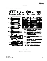
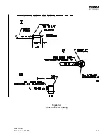
Page 25: ...Revision B December 16 1996 3 3 Figure 3 2 Coax Connector Drawing ...
Page 26: ...3 4 Revision A November 25 1996 THIS PAGE INTENTIONALLY LEFT BLANK ...
Page 27: ...Revision A November 25 1996 3 5 Figure 3 3 Adjustment Locations ...
Page 28: ...3 6 Revision A November 25 1996 THIS PAGE INTENTIONALLY LEFT BLANK ...
Page 29: ...Revision A November 25 1996 3 7 Figure 3 4 VOX Jumper Locations ...
Page 30: ...3 8 Revision A November 25 1996 THIS PAGE INTENTIONALLY LEFT BLANK ...
Page 31: ...Revision A November 25 1996 Figure 3 5 Sheet 1 of 2 Outline Dimensions 3 9 10 ...
Page 32: ...Revision A November 25 1996 Figure 3 5 Sheet 2 of 2 Outline Dimensions 3 11 12 ...
Page 33: ...Revision A November 25 1996 Figure 3 6 Interconnect Diagram 3 13 14 ...
Page 39: ...4 6 Revision A November 25 1996 Figure 4 1 Front Panel Controls ...
Page 41: ...5 2 Revision A November 25 1996 THIS PAGE INTENTIONALLY LEFT BLANK ...
Page 43: ...6 2 Revision A November 25 1996 6 2 INSTALLATION NOTES ...


