background image

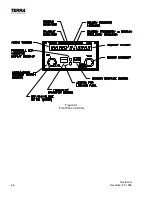
Revision A
November 25, 1996

3-5

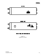
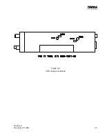
Figure 3-3

Adjustment Locations

Summary of Contents for TX 760D

Page 1: ...OPERATION INSTALLATION MANUAL Trimble 2105 Donley Austin Texas 78758 512 432 0400 PUBLICATION NUMBER 82619 PRINTED IN U S A TX 760D VHF COMMUNICATION TRANSCEIVER ...

Page 2: ...ERATION INSTALLATION MANUAL Trimble 2105 Donley Austin Texas 78758 512 432 0400 DECEMBER 16 1996 PUBLICATION NUMBER 82619 REVISION B PRINTED IN U S A TX 760D VHF COMMUNICATIONS TRANSCEIVER T 1 Title Page ...

Page 3: ...r 25 1996 Record of Revisions B November 25 1996 Table of Contents Main TC 1 TC 2 November 25 1996 Section I Introduction 1 1 1 4 November 25 1996 Section II Installation 2 1 2 10 November 25 1996 Section III Installation Drawings 3 1 3 14 November 25 1996 Section IV Operation 4 1 4 6 November 25 1996 Section V Warranty 5 1 5 2 November 25 1996 Section VI Installation Bulletins Notes 6 1 6 2 Novem...

Page 4: ...evision A November 25 1996 Terra by Trimble TX 760DVHF Communication Transceiver Assigned To Job Title Location RECORD OF REVISIONS Rev Revision Insertion Rev Revision Insertion By By No Date Date No Date Date ...

Page 5: ... equipment before If yes are you satisfied with the equipment and customer service What were your two most important reasons for selecting Trimble avionics ______________________________________________________________________________________ ______________________________________________________________________________________ What are the two aviation related publications you read most often ___...

Page 6: ...____________________________________ ______________________________________ Place Stamp Here ______________________________________ ______________________________________ Trimble 2105 Donley Drive Austin TX 78758 FOLD FOLD ...

Page 7: ...ONS FOR AVIONICS 2 1 2 4 INSTALLATION 2 5 2 5 ANTENNA INSTALLATION 2 9 2 6 OPERATIONAL CHECKOUT 2 9 2 7 FINAL INSPECTION 2 7 SECTION III 3 1 3 INSTALLATION DRAWINGS 3 1 SECTION IV 4 1 4 OPERATION 4 1 4 1 SCOPE 4 1 4 2 OPERATION 4 1 4 3 FREQUENCY MODE 4 1 4 4 NORMAL OPERATION 4 1 4 5 FREQUENCY TRANSFER 4 2 4 6 COMM TUNING KNOB OPERATING SEQUENCE 4 2 4 7 MEM MEMORY OPERATING SEQUENCE 4 2 4 8 TO PROG...

Page 8: ...on A November 25 1996 SECTION V 5 1 5 WARRANTY 5 1 5 1 LIMITED WARRANTY OF TERRA BY TRIMBLE PRODUCTS 5 1 SECTION VI 6 1 6 INSTALLATION BULLETINS NOTES 6 1 6 1 INSTALLATION BULLETINS 6 1 6 2 INSTALLATION NOTES 6 2 ...

Page 9: ... state antenna switching switching power supply with overload protection and microprocessor controlled frequency selection and monitoring make the TX 760D a reliable answer to today s communicationrequirements The transceiver can be mounted in two different configurations in a single tray or in a dual tray All power and control connections are made through a 15 pin D type connector installed on th...

Page 10: ... REQUIREMENTS The Terra by Trimble TX 760D transceiver requires 13 75 VDC 10 20 input at 2 5 amps maximum load condition 1 3 3 ENVIRONMENTAL SPECIFICATIONS MaximumOperatingConditions Altitude To 30 000 feet 9 150 meters Humidity To 95 at 50 C 122 F Temperature Range 20 C 4 F to 55 C 131 F Vibration 0 5 G from 5 to 500 Hz 1 3 4 ELECTRICAL SPECIFICATIONS All specifications at 13 75 VDC nominal RECEI...

Page 11: ...nominal SpuriousResponses Greater than 50 dBm below carrier level Sidetone Up to 25 milliwatts into 600 headphones FCCApproval Type accepted per FCC Part 87 1 4 EQUIPMENT SUPPLIED The equipment supplied will depend upon the system you have ordered The part numbers and descriptions listed below indicate the equipment supplied with the TX 760D only If a system other than those listed below was order...

Page 12: ...ient to make the harness 3 Microphone and headphone jacks as required 4 Circuit breaker rated at 4 amps 5 50 ohm communications antenna rated at top speed of the aircraft 1 6 LICENSE REQUIREMENTS The operator of the Terra by Trimble TX 760D transceiver is required by the Federal Communications Commission to hold a restricted radio telephone operator s permit or a higher class of license A U S citi...

Page 13: ...it for service or to transfer it to another location 2 3 GENERAL INSTALLATION INSTRUCTIONS FOR AVIONICS The following paragraphs contain pertinent hints advice and guidance intended for use by installers of avionics equipment These have been drafted to address common problems encountered during the installation process Specific questions may be addressed to Trimble for technical assistance by call...

Page 14: ...na gain radiation pattern in the direction of the restriction For example if an antenna is mounted less than 21 inches from the edge of a ground plane surface then both the range of reception and transmission to that direction will be reduced in direct correlation with how much closer than 21 inches that antenna is mounted from the edge Another undesirable antenna placement occurs when a VHF commu...

Page 15: ... with existing avionics instruments or controls Remove the connector plates from the rear of the trays Connect all wires to the proper pin of each connector checking as you go to insure that no loose strands cause shorting to adjacent pins or to ground surfaces We recommend tubing be placed over each soldered pin connection to prevent wire strands from touching adjacent connections Be particularly...

Page 16: ...e avionics master and at the affected unit for noise on the power line If present try to categorize the frequency eg alternator whine which may be caused by one or more bad alternator diodes or if interference is present only when a communication unit is transmitting etc If the noise is present or worse at the affected unit than at the avionics master investigate the harness for noise coupling bet...

Page 17: ...here is simply not enough space to provide ground plane or antenna separation as recommended Or the aircraft strobe noise is audible but not objectionable etc These problems should be discussed early and thoroughly with the customer 2 3 5 SUMMARY The paragraphs above are not intended to be highly technical completely thorough or extensive but serve as a reminder for certain precautionary or follow...

Page 18: ...re that the sleeve is installed with the largest opening toward the top 6 The 15 pin D connector assembly supplied with the Terra by Trimble TX 760D must be wired correctly to the aircraft avionics systems or severe damage may result to the Terra by Trimble TX 760D or other systems The interconnecting wiring for the 15 pin D connector is shown in Figure 3 6 Comply with standards set forth in FAA A...

Page 19: ...rawing Figure 3 4 9 Yet another option for use with the VOX Intercom feature is an external VOX Intercom volume adjustment This requires a potentiometer 10 k 1 4 W Audio taper to be installed as per note 6 on Figure 3 6 When using this option the VOX Intercom volume adjustment on the TX 760D must be fully CW and shorting jumper SJ602 removed for proper operation SJ602 can be located using componen...

Page 20: ...If the VOX Intercom is breaking on ambient noise or is not breaking soon enough the VOX Intercom squelch adjustment is used Turning counterclockwise will allow the squelch to break at lower microphone levels and turning clockwise will require more microphone audio to break squelch NOTE If using the External VOX Intercom squelch adjust option this adjustment must be turned fully CCW and shorting ju...

Page 21: ...ONAL CHECK OUT 1 Rotate volume control small inner left hand knob clockwise to turn transceiver on 2 Rotate Tune right hand knob to obtain desired frequency in right hand window Verify that the faster the knob is rotated the more the frequency changes with each detent 3 Press the TRANSFER button and verify that the two frequencies swap sides in the display 4 Adjust squelch control large outer left...

Page 22: ... While slowly returning yoke to its normal position rotate yoke left and right to insure all cabling is routed and tied up properly Cycle rudder pedals and verify that they are free and cables are unobstructed Install gust locks perform complete check out of all avionics including dimmers Secure aircraft power and all master switches 2 Have installation inspected by someone authorized under Federa...

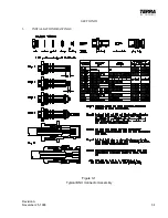
Page 23: ...Revision A November 25 1996 3 1 SECTION III 3 INSTALLATION DRAWINGS Figure 3 1 Typical BNC Connector Assembly ...

Page 24: ...3 2 Revision A November 25 1996 THIS PAGE INTENTIONALLY LEFT BLANK ...

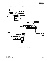
Page 25: ...Revision B December 16 1996 3 3 Figure 3 2 Coax Connector Drawing ...

Page 26: ...3 4 Revision A November 25 1996 THIS PAGE INTENTIONALLY LEFT BLANK ...

Page 27: ...Revision A November 25 1996 3 5 Figure 3 3 Adjustment Locations ...

Page 28: ...3 6 Revision A November 25 1996 THIS PAGE INTENTIONALLY LEFT BLANK ...

Page 29: ...Revision A November 25 1996 3 7 Figure 3 4 VOX Jumper Locations ...

Page 30: ...3 8 Revision A November 25 1996 THIS PAGE INTENTIONALLY LEFT BLANK ...

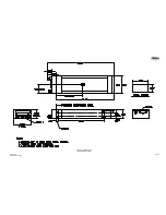
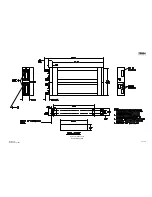
Page 31: ...Revision A November 25 1996 Figure 3 5 Sheet 1 of 2 Outline Dimensions 3 9 10 ...

Page 32: ...Revision A November 25 1996 Figure 3 5 Sheet 2 of 2 Outline Dimensions 3 11 12 ...

Page 33: ...Revision A November 25 1996 Figure 3 6 Interconnect Diagram 3 13 14 ...

Page 34: ...eases the frequency and counterclockwise tuning decreases the frequency At the upper and lower limits of the frequency band i e 118 00 and 136 975 the frequency will wrap around This allows faster tuning from one end of the band to the other After the desired frequency is obtained simply press the TRANSFER button to move the new frequency into the left hand or active window and your previously use...

Page 35: ...he end of the frequency range up or down will cause the frequency to wrap around to the other end of the range e g scrolling up past 136 wraps to 118 C Pushing the knob again for approximately one third of a second will shift the cursor control from MHz to kHz Example 1XX XX causing the MHz digits to light steady and the kHz digits to blink D In the same manner as above rotating the knob will now ...

Page 36: ... knob first and then the MEM button Hold both in for approximately four seconds The display will go into a blank condition B If the display has blanked moving the tuning control pressing the button pressing the MEM button Keying the transmitter will restore the display Specifically the first press of the button the first click or first push of the tuning knob will restore the display with no chang...

Page 37: ...lows a user to set the VOX Intercom squelch for different conditions in the cockpit i e full throttle and cruise Also all TX 760D s have the option of both the squelch and a user adjustable external VOX Intercom volume control This allows the user to set both the volume and squelch levels for different conditions in the cockpit See Section 2 4 12 for more information on these features 4 11 EMERGEN...

Page 38: ...porated in your TX 760D Should the left hand display start flashing and the code 01 appear in the right hand display the synthesizer is not tuned and will not channel the unit Power down wait 5 seconds and power up If the unit will not reset service is required If the left hand display is flashing and a 02 code is produced in the right hand display the unit has shut down due to excessive continuou...

Page 39: ...4 6 Revision A November 25 1996 Figure 4 1 Front Panel Controls ...

Page 40: ...nd installed Also note your name address daytime telephone number and a description of the defect Ship the equipment UPS or equivalent You must prepay the shipping charges Ship to Trimble 2105 Donley Dr Austin TX 78758 512 432 0400 Phone 512 836 9413 FAX We will pay surface shipping charges to return the equipment to you What does your warranty not cover What does your warranty not cover What does...

Page 41: ...5 2 Revision A November 25 1996 THIS PAGE INTENTIONALLY LEFT BLANK ...

Page 42: ...Revision A November 25 1996 6 1 SECTION VI 6 INSTALLATION BULLETINS NOTES 6 1 INSTALLATION BULLETINS ...

Page 43: ...6 2 Revision A November 25 1996 6 2 INSTALLATION NOTES ...

Reviews: