Revision A
November 25, 1996
4-5
4.12
BLIND OPERATION
In the unlikely event of a display failure, power the unit down for a few seconds. Upon power
up, wait 5 seconds for the unit to initialize. Press the "MEM" button once. This will recall
121.50 into the "standby" window. Pressing the Transfer key "<—>"makes this memory
frequency active.
If a record has been made of the frequencies that you have stored within the memories, the
same method as above will work with any memory location. Remember, whenever the TX
760D is turned on it always starts on memory location "Om." Thus, any memory location
can be seleted by incrementing the memory counting the steps. Pressing the "MEM" button
will increment the memory location once per key press.
Pressing the transfer key "<—>" makes this memory frequency active.
4.13
FAILURE MODE OPERATION
There are two failure mode annunciations incorporated in your TX 760D. Should the left-
hand display start flashing and the code 01 appear in the right-hand display, the synthesizer is
not tuned and will not channel the unit. Power down, wait 5 seconds, and power up. If the
unit will not reset, service is required.
If the left hand display is flashing and a "02" code is produced in the right hand display, the
unit has shut down due to excessive continuous transmission time. Continuous transmissions
longer than 30 seconds will produce this code. To clear the error code, unkey the transmitter.
If normal operatin is not restored, power the unit down, wait one minute and power the unit
up. If the “T” is seen to the right side of the active display, the mic keyline is stuck.
4.14
SAFEGUARDS OPERATION
In order to remind the operator that the unit is receiving and the volume may not be turned
up, an “R” is displayed to the right of the active display. This “R” will come on anytime a
signal is being received or squelch is “broken”.
Also to remind the operator, a “T” will be displayed any time the unit is in the transmit mode.
Summary of Contents for TX 760D
Page 24: ...3 2 Revision A November 25 1996 THIS PAGE INTENTIONALLY LEFT BLANK ...
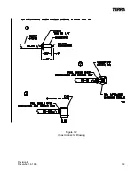
Page 25: ...Revision B December 16 1996 3 3 Figure 3 2 Coax Connector Drawing ...
Page 26: ...3 4 Revision A November 25 1996 THIS PAGE INTENTIONALLY LEFT BLANK ...
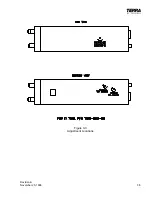
Page 27: ...Revision A November 25 1996 3 5 Figure 3 3 Adjustment Locations ...
Page 28: ...3 6 Revision A November 25 1996 THIS PAGE INTENTIONALLY LEFT BLANK ...
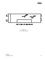
Page 29: ...Revision A November 25 1996 3 7 Figure 3 4 VOX Jumper Locations ...
Page 30: ...3 8 Revision A November 25 1996 THIS PAGE INTENTIONALLY LEFT BLANK ...
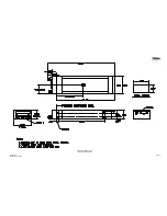
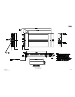
Page 31: ...Revision A November 25 1996 Figure 3 5 Sheet 1 of 2 Outline Dimensions 3 9 10 ...
Page 32: ...Revision A November 25 1996 Figure 3 5 Sheet 2 of 2 Outline Dimensions 3 11 12 ...
Page 33: ...Revision A November 25 1996 Figure 3 6 Interconnect Diagram 3 13 14 ...
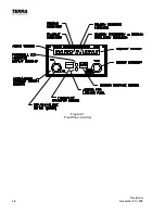
Page 39: ...4 6 Revision A November 25 1996 Figure 4 1 Front Panel Controls ...
Page 41: ...5 2 Revision A November 25 1996 THIS PAGE INTENTIONALLY LEFT BLANK ...
Page 43: ...6 2 Revision A November 25 1996 6 2 INSTALLATION NOTES ...


