2-8
Revision A
November 25, 1996
2.4
INSTALLATION (Continued)
11.
The connector is mounted from the front side of the sleeve with two Phillips head
screws and lock washers. As viewed from the front of the unit, pin 1 of the
connector is top right and pin 15 is bottom left.
12.
The following items are preset at the factory to nominal levels, but individual pilot
desires and installations may require field adjustments. For these adjustments, access
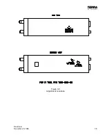
holes have been provided in the covers of the TX 760D. Figure 3-3 shows the
locations of these access holes.
A.
Sidetone Volume
If the installation requires more (or less) volume into the headphones during
transmit the sidetone volume adjustment is used. Turning clockwise will
increase the volume and turning counterclockwise will decrease the volume.
B.
VOX Intercom Squelch
If the VOX Intercom is breaking on ambient noise or is not breaking soon
enough the VOX Intercom squelch adjustment is used. Turning
counterclockwise will allow the squelch to break at lower microphone levels
and turning clockwise will require more microphone audio to break squelch.
NOTE:
If using the External VOX Intercom squelch adjust option this adjustment
must be turned fully CCW and shorting jumper SJ601 removed for proper
operation of the External VOX squelch adjustment.
C.
Intercom Volume
If the installation requires more (or less) intercom volume into the
headphones the Intercom Volume adjustment is used. Turning
counterclockwise will decrease the headphone volume level and turning
clockwise will increase the headphone volume level.
NOTE:
If using the external VOX Intercom volume adjust option, this adjustment
must be turned fully CW and shorting jumper SJ602 removed for proper
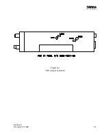
operation of the external VOX Intercom volume adjustment. See
Component Locator, Figure 3-4 for location of SJ601 and SJ602.
Summary of Contents for TX 760D
Page 24: ...3 2 Revision A November 25 1996 THIS PAGE INTENTIONALLY LEFT BLANK ...
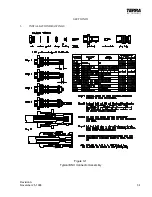
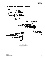
Page 25: ...Revision B December 16 1996 3 3 Figure 3 2 Coax Connector Drawing ...
Page 26: ...3 4 Revision A November 25 1996 THIS PAGE INTENTIONALLY LEFT BLANK ...
Page 27: ...Revision A November 25 1996 3 5 Figure 3 3 Adjustment Locations ...
Page 28: ...3 6 Revision A November 25 1996 THIS PAGE INTENTIONALLY LEFT BLANK ...
Page 29: ...Revision A November 25 1996 3 7 Figure 3 4 VOX Jumper Locations ...
Page 30: ...3 8 Revision A November 25 1996 THIS PAGE INTENTIONALLY LEFT BLANK ...
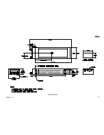
Page 31: ...Revision A November 25 1996 Figure 3 5 Sheet 1 of 2 Outline Dimensions 3 9 10 ...
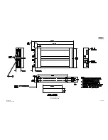
Page 32: ...Revision A November 25 1996 Figure 3 5 Sheet 2 of 2 Outline Dimensions 3 11 12 ...
Page 33: ...Revision A November 25 1996 Figure 3 6 Interconnect Diagram 3 13 14 ...
Page 39: ...4 6 Revision A November 25 1996 Figure 4 1 Front Panel Controls ...
Page 41: ...5 2 Revision A November 25 1996 THIS PAGE INTENTIONALLY LEFT BLANK ...
Page 43: ...6 2 Revision A November 25 1996 6 2 INSTALLATION NOTES ...


