2-2
Revision A
November 25, 1996
2.3.2
ANTENNAS
The three cardinal points for antenna installation are location, mounting and
electrical characteristics.
Antenna Location:
Select a location that provides an adequate ground plane, a continuous unbroken
surface of metal. At VHF frequencies, a minimum of a 42 inch diameter circle with
the antenna at center is recommended. Provide an area where shadowing of the
antenna will not occur (eg. blocking of the signal by other parts of the aircraft).
Remember that at VHF frequencies and above, direct line of sight signals are
required from ground stations to the antenna for maximum effective range. Consider
that close proximity of an antenna to other antennas or noise sources may create
interference problems. Read carefully and follow closely the recommendations of
the antenna manufacturer about antenna location.
It is particularly important for VHF communication antennas that the 42 inch
diameter ground plane area be provided for each antenna, and the ground plane
surface must be relatively flat. Serious problems are often encountered in aircraft
which include composite materials or fabric surfaces and in many cases ground plane
should be added if normal communication range is to be achieved.
The effect of a limited or restricted ground plane is a severe reduction of the antenna
gain radiation pattern in the direction of the restriction. For example, if an antenna is
mounted less than 21 inches from the edge of a ground plane surface, then both the
range of reception and transmission to that direction will be reduced in direct
correlation with how much closer than 21 inches that antenna is mounted from the
edge.
Another undesirable antenna placement occurs when a VHF communication antenna
is placed within 21 inches from a second VHF communication antenna, or within 21
inches of the metallic vertical edge of the tail assembly, etc. The effect is reduction
of antenna gain radiation pattern to the direction of the other antenna or the vertical
edge. The 21 inch separation is an absolute minimum!
Antenna Mounting:
Proper attachment of any antenna to the aircraft surface is of primary importance.
Carefully clean all paint and corrosion off the mounting surface and apply an anti-
corrosion treatment. Do the same to the inside surface if a backing or nut plate is to
be used. Mount the antenna securely per the antenna manufacturer’s
recommendations and check carefully to insure good electrical bonding. Do not
mount any antenna to doors, hatches, inspection plates or other moveable surfaces
because proper bonding to the aircraft surface cannot be accomplished. After proper
mounting and bonding is achieved, a bead of high quality RTV around the junction
of the antenna base and the aircraft surface will prevent water seepage and corrosion
from forming between the antenna base and aircraft surface.
Summary of Contents for TX 760D
Page 24: ...3 2 Revision A November 25 1996 THIS PAGE INTENTIONALLY LEFT BLANK ...
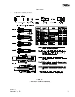
Page 25: ...Revision B December 16 1996 3 3 Figure 3 2 Coax Connector Drawing ...
Page 26: ...3 4 Revision A November 25 1996 THIS PAGE INTENTIONALLY LEFT BLANK ...
Page 27: ...Revision A November 25 1996 3 5 Figure 3 3 Adjustment Locations ...
Page 28: ...3 6 Revision A November 25 1996 THIS PAGE INTENTIONALLY LEFT BLANK ...
Page 29: ...Revision A November 25 1996 3 7 Figure 3 4 VOX Jumper Locations ...
Page 30: ...3 8 Revision A November 25 1996 THIS PAGE INTENTIONALLY LEFT BLANK ...
Page 31: ...Revision A November 25 1996 Figure 3 5 Sheet 1 of 2 Outline Dimensions 3 9 10 ...
Page 32: ...Revision A November 25 1996 Figure 3 5 Sheet 2 of 2 Outline Dimensions 3 11 12 ...
Page 33: ...Revision A November 25 1996 Figure 3 6 Interconnect Diagram 3 13 14 ...
Page 39: ...4 6 Revision A November 25 1996 Figure 4 1 Front Panel Controls ...
Page 41: ...5 2 Revision A November 25 1996 THIS PAGE INTENTIONALLY LEFT BLANK ...
Page 43: ...6 2 Revision A November 25 1996 6 2 INSTALLATION NOTES ...


