


Revision H
August 19, 1996
5
SECTION II
2.
INSTALLATION
2.1
GENERAL
This section contains all necessary installation instructions and checkout procedures for the
Terra by Trimble TN 200D Navigational Receiver.
2.2
PREPARATION FOR USE
Every precaution has been taken to protect the TN 200D during shipment. Upon receipt of
the equipment, perform the following inspections:
1.
Remove the unit from the shipping container and visually inspect for damage.
2.
Check controls and switches to determine if they may have been damaged.
3.
Make sure that all hardware and connectors listed in Section I, under “Equipment
Supplied”, are present.
If the unit is damaged, a claim must be filed with the carrier. The carrier assumes title of the
unit when it accepts it for shipment. Do not return it to Trimble or its representatives.
It is suggested that the package be retained for inspection by the carrier in the case of
damage or for future use should it be necessary to ship the unit for service or to transfer it to
another location.
2.3
GENERAL INSTALLATION INSTRUCTIONS FOR AVIONICS
The following paragraphs contain pertinent hints, advice, and guidance intended for use by
installers of avionics equipment. These have been drafted to address common problems
encountered during the installation process. Specific questions may be addressed to Trimble
for technical assistance by calling 1-800-487-4662 and requesting Technical Assistance.
2.3.1
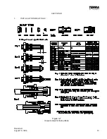
COAXIAL CABLES AND CONNECTORS
Improper installation of coaxial cables and connectors create many of the problems
encountered during avionics installations. Refer to Figure3-1 for guidance of typical
BNC connector assembly. Refer to Figure 3-2 for instructions about connecting coax
cable to the BNC connector(s) mounted at the rear of Terra by Trimble mounting
trays. Problems to avoid include twisted, chafed, or pinched cables, sharp bends in
cables, open or shorted center conductors or shield braid, and improper grounding of
shields. Also, proper termination of antenna coaxial cables at the antenna should be
carefully checked. After installing connectors, pull firmly to ensure good mechanical
bonding (particularly if you use crimp-on connectors) and use your ohmmeter to
insure good electrical connection with no shorting. Be sure that coax lengths and
types follow the avionics manufacturer’s recommendations.
Summary of Contents for TN 200D
Page 16: ...12 Revision H August 19 1996 THIS PAGE INTENTIONALLY LEFT BLANK ...
Page 18: ...14 Revision H August 19 1996 THIS PAGE INTENTIONALLY LEFT BLANK ...
Page 19: ...Revision H August 19 1996 15 Figure 3 2 Coax Connector Instructions ...
Page 20: ...16 Revision H August 19 1996 THIS PAGE INTENTIONALLY LEFT BLANK ...
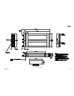
Page 21: ...Revision H August 19 1996 17 18 Figure 3 3 TN 200D Outline Dimensions ...
Page 22: ...Revision H August 19 1996 19 20 Figure 3 4 Typical Outline Drawing Dual Tray ...
Page 23: ...Revision H August 19 1996 21 22 Figure 3 5 Outline Drawing 3 Option ...
Page 24: ...Revision H August 19 1996 23 24 Figure 3 6 Interconnect Drawing TN 200D Without Glideslope ...
Page 25: ...Revision H August 19 1996 25 26 Figure 3 7 Interconnect Diagram TN 200D With Glideslope ...
Page 33: ...34 Revision H August 19 1996 THIS PAGE INTENTIONALLY LEFT BLANK ...
Page 35: ...36 Revision H August 19 1996 THIS PAGE INTENTIONALLY LEFT BLANK ...
Page 37: ...38 Revision H August 19 1996 6 2 INSTALLATION NOTES ...


