


28
Revision H
August 19, 1996
4.5
ILS AND DME CHANNELING OPERATION
If your TN 200D is equipped with the glideslope receiver, anytime an ILS frequency is
selected in the active window the glideslope receiver is automatically channeled to the
appropriate frequency. At all times DME channeling is being produced on the glideslope
board.
4.6
FREQUENCY TRANSFER
As previously described in Section 4.3, simply pressing this button will “swap” frequencies
between active and standby windows.
As will be covered in the next section, depressing this button also cancels the channel
memory display.
The transfer button must be used in order for the last used frequencies to be displayed after a
power interruption. For example, say you are tuned to 108.00 in the active display and
116.60 in the standby display. Pressing the transfer button will insure that the unit will
display 116.60 108.00 after any power interruptions. Failure to do this transfer will cause
the unit to come up with 108.00 in the active display and the last transferred frequency in the
standby display.
4.7
TO PLACE FREQUENCIES IN MEMORY
The TN 200D has a 10 user programmable memories. To place frequencies in memory, push
the tune knob in. In between the active and standby window, “O” will be displayed. After
rotating the tune knob 1 detent from “O” an “M” will appear in the display beside the
number. Rotating the tune knob, while holding it in, will increment or decrement the channel
number from 0 through 9 or vice-versa. After you obtain the desired channel number, simply
release the knob and rotate the tune knob to your desired storage frequency. Press the “STO”
(STORE) button and that frequency is now entered in the indicated channel memory.
EXAMPLE:
At your airport, the following frequencies are used:
VOR
113.20
ILS Approach
110.30
For simplicity, lets assign channel numbers in this same order. To enter these in memory,
follow these steps:
Push tune knob:
XXX.XX 0
XXX.XX
Hold in and rotate:
XXX.XX 1m XXX.XX
Release and tune:
XXX.XX 1
113.20
Press “STO”:
XXX.XX 1m 113.20
Push tune knob and hold:
XXX.XX 1m 113.20
Summary of Contents for TN 200D
Page 16: ...12 Revision H August 19 1996 THIS PAGE INTENTIONALLY LEFT BLANK ...
Page 18: ...14 Revision H August 19 1996 THIS PAGE INTENTIONALLY LEFT BLANK ...
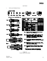
Page 19: ...Revision H August 19 1996 15 Figure 3 2 Coax Connector Instructions ...
Page 20: ...16 Revision H August 19 1996 THIS PAGE INTENTIONALLY LEFT BLANK ...
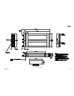
Page 21: ...Revision H August 19 1996 17 18 Figure 3 3 TN 200D Outline Dimensions ...
Page 22: ...Revision H August 19 1996 19 20 Figure 3 4 Typical Outline Drawing Dual Tray ...
Page 23: ...Revision H August 19 1996 21 22 Figure 3 5 Outline Drawing 3 Option ...
Page 24: ...Revision H August 19 1996 23 24 Figure 3 6 Interconnect Drawing TN 200D Without Glideslope ...
Page 25: ...Revision H August 19 1996 25 26 Figure 3 7 Interconnect Diagram TN 200D With Glideslope ...
Page 33: ...34 Revision H August 19 1996 THIS PAGE INTENTIONALLY LEFT BLANK ...
Page 35: ...36 Revision H August 19 1996 THIS PAGE INTENTIONALLY LEFT BLANK ...
Page 37: ...38 Revision H August 19 1996 6 2 INSTALLATION NOTES ...


