


Revision H
August 19, 1996
31
4.4A
IDENT OPERATION
Whenever the left hand knob is depressed the ident is eliminated from the audio output and
only voice is heard. With the knob pulled out the voice and ident are heard.
4.5A
ILS AND DME CHANNELING OPERATION
If your TN 200D is equipped with the glideslope receiver, anytime an ILS frequency is
selected in the active window the glideslope receiver is automatically channeled to the
appropriate frequency. At all times DME channeling is being produced on the glideslope
board.
4.6A
MEMORY OPERATION
Pressing the MEM button will call up the last used or programmed memory position.
Repeatedly pushing the MEM button will cycle upwards through the memory positions.
Alternately, holding the MEM button in will cause the unit to cycle through the memory
positions at a rate of one position every one-third of a second.
4.7A
TO PROGRAM NEW FREQUENCIES IN MEMORY
Press MEM to select the desired memory position. The “M” will illuminate between active
and standby frequencies. Tune the new frequency using either the continuous or cursor
programming method. As soon as the frequency value changes from the stored frequency, the
“M” light goes out.
Press MEM again to store the new frequency. The “M” relights to confirm storage.
Use the button to move the new memory frequency to active side and repeat these steps to
store additional frequencies in memory.
Note:
If the button is pressed before storing the new frequency into memory; the
radio will drop out of program mode and the new frequency will not be
stored.
Summary of Contents for TN 200D
Page 16: ...12 Revision H August 19 1996 THIS PAGE INTENTIONALLY LEFT BLANK ...
Page 18: ...14 Revision H August 19 1996 THIS PAGE INTENTIONALLY LEFT BLANK ...
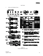
Page 19: ...Revision H August 19 1996 15 Figure 3 2 Coax Connector Instructions ...
Page 20: ...16 Revision H August 19 1996 THIS PAGE INTENTIONALLY LEFT BLANK ...
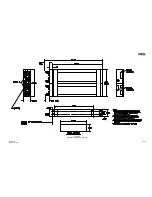
Page 21: ...Revision H August 19 1996 17 18 Figure 3 3 TN 200D Outline Dimensions ...
Page 22: ...Revision H August 19 1996 19 20 Figure 3 4 Typical Outline Drawing Dual Tray ...
Page 23: ...Revision H August 19 1996 21 22 Figure 3 5 Outline Drawing 3 Option ...
Page 24: ...Revision H August 19 1996 23 24 Figure 3 6 Interconnect Drawing TN 200D Without Glideslope ...
Page 25: ...Revision H August 19 1996 25 26 Figure 3 7 Interconnect Diagram TN 200D With Glideslope ...
Page 33: ...34 Revision H August 19 1996 THIS PAGE INTENTIONALLY LEFT BLANK ...
Page 35: ...36 Revision H August 19 1996 THIS PAGE INTENTIONALLY LEFT BLANK ...
Page 37: ...38 Revision H August 19 1996 6 2 INSTALLATION NOTES ...


