Revision H
August 19, 1996
7
2.3.3
WIRING AND HARNESSING
Construct the installation wiring harness carefully from the avionics manufacturer’s
wiring diagram. Be extremely careful to note recommended wire sizes, the need for
shielded wiring (if any), and decide upon any optional wiring to be included. Measure
carefully and plan the harness layout to avoid interference of the cable harness with
existing avionics, instruments or controls.
Remove the connector plates from the rear of the trays. Connect all wires to the
proper pin of each connector, checking as you go to insure that no loose strands cause
shorting to adjacent pins or to ground surfaces. We recommend tubing be placed
over each soldered pin connection to prevent wire strands from touching adjacent
connections. Be particularly careful with the shield braids of shielded wires. Do not
expose any more of the conductor than is absolutely necessary and keep the braid
connection as short as possible. Remember that on shielded wires only one ground
point is recommended. Follow manufacturer’s recommendation about where the
ground point should be located. After completing all connections, check wiring
with an ohmmeter again to ascertain that all connections are as desired and
that no undesired shorting to ground or other pins has occurred. Visually
double check to see that braids on shields are not creating shorting that no insulator
melting has occurred during soldering and pull firmly on all connections to insure good
mechanical bond.
Install the harness and connectors/connector plates in the aircraft with very loose
dress only.
Solder all connections to power and ground and install panel components/controls and
safety devices (eg. fuses or breakers). It is desirable at this point to insert all
equipment in trays and perform preliminary check-out. Following a satisfactory
check-out, and with all equipment in the properly installed location, complete the final
dressing and routing of the harness and secure in place.
Note:
It is extremely important that units should be installed in trays while final dress
and bundling of the harness is accomplished to assure proper alignment of
connectors between tray and unit. Failure to do this may cause problems
when unit is initially inserted into tray due to misalignment of connectors!
The final step is to perform a complete check of all avionics operations and insure that
free movement of all cockpit controls is available.
2.3.4
NOISE AND INTERFERENCE
The typical airframe is a small and imperfect platform for providing all of the antenna
ground planes and power sources and inter-wiring required for avionics operations,
particularly for a low noise and interference free expectation. This subject is far too
broad and complex to address in detail in a few paragraphs. However, an approach
to categorizing and defining the problem can be outlined.
Summary of Contents for TN 200D
Page 16: ...12 Revision H August 19 1996 THIS PAGE INTENTIONALLY LEFT BLANK ...
Page 18: ...14 Revision H August 19 1996 THIS PAGE INTENTIONALLY LEFT BLANK ...
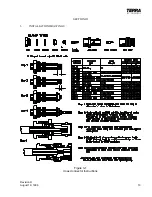
Page 19: ...Revision H August 19 1996 15 Figure 3 2 Coax Connector Instructions ...
Page 20: ...16 Revision H August 19 1996 THIS PAGE INTENTIONALLY LEFT BLANK ...
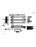
Page 21: ...Revision H August 19 1996 17 18 Figure 3 3 TN 200D Outline Dimensions ...
Page 22: ...Revision H August 19 1996 19 20 Figure 3 4 Typical Outline Drawing Dual Tray ...
Page 23: ...Revision H August 19 1996 21 22 Figure 3 5 Outline Drawing 3 Option ...
Page 24: ...Revision H August 19 1996 23 24 Figure 3 6 Interconnect Drawing TN 200D Without Glideslope ...
Page 25: ...Revision H August 19 1996 25 26 Figure 3 7 Interconnect Diagram TN 200D With Glideslope ...
Page 33: ...34 Revision H August 19 1996 THIS PAGE INTENTIONALLY LEFT BLANK ...
Page 35: ...36 Revision H August 19 1996 THIS PAGE INTENTIONALLY LEFT BLANK ...
Page 37: ...38 Revision H August 19 1996 6 2 INSTALLATION NOTES ...


