background image

Revision H
August 19, 1996

37

SECTION VI

6.

INSTALLATION BULLETINS/NOTES

6.1

INSTALLATION BULLETINS

Place any installation bulletins after this page and record below:

DATE

BULLETIN NUMBER

DESCRIPTION

ENTERED BY

Summary of Contents for TN 200D

Page 1: ...OPERATION INSTALLATION MANUAL Trimble 2105 Donley Austin Texas 78758 512 432 0400 PUBLICATION NUMBER 1910 0007 01 PRINTED IN U S A TN 200D NAVIGATIONAL RECEIVER ...

Page 2: ...OPERATION INSTALLATION MANUAL Trimble 2105 Donley Austin Texas 78758 512 432 0400 AUGUST 19 1996 PUBLICATION NUMBER 1910 0007 01 REVISION H PRINTED IN U S A TN 200D NAVIGATIONAL RECEIVER T 1 Title Page ...

Page 3: ...NERAL 5 2 2 PREPARATION FOR USE 5 2 3 GENERAL INSTALLATION INSTRUCTIONS FOR AVIONICS 5 2 4 INSTALLATION 9 2 5 ANTENNA INSTALLATION 10 2 6 OPERATIONAL CHECKOUT 10 2 7 FINAL INSPECTION 11 SECTION III 13 3 INSTALLATION DRAWINGS 13 SECTION IV 27 4 OPERATION 27 BELOW MOD 2 W O GLIDESLOPE BELOW MOD 3 W GLIDESLOPE 4 1 SCOPE 27 4 2 OPERATION 27 4 3 FREQUENCY MODE 27 4 4 IDENT OPERATION 27 4 5 ILS AND DME ...

Page 4: ...NG KNOB OPERATION 30 4 4A IDENT OPERATION 31 4 5A ILS AND DME CHANNELING OPERATION 31 4 6A MEMORY OPERATION 31 4 7A TO PLACE FREQUENCIES IN MEMORY 31 4 8A DISPLAY BLANKING OPERATION 32 SECTION V 35 5 LIMITED WARRANTY OF TERRA BY TRIMBLE PRODUCTS 35 5 1 WARRANTY 35 SECTION VI 37 6 INSTALLATION BULLETINS NOTES 37 6 1 INSTALLATION BULLETINS 37 6 2 INSTALLATION NOTES 38 ...

Page 5: ...uble tray or in a 3 ATI hole using the 3 adapter With tray mounted units all power and control connections are made to a 15 pin D type connector installed in the rear of the mounting tray A standard BNC male chassis connector is supplied on the tray for antenna connections For the 3 option a locking hooded 15 pin D type connector and standard BNC male connector are used respectively for power cont...

Page 6: ...ectors Antenna input BNC Interconnect cable 15 pin D type 1 3 2 POWER REQUIREMENTS The Terra by Trimble TN 200D navigational receiver requires 13 75 VDC input 10 20 at 0 6 amps under maximum load conditions 1 3 3 ENVIRONMENTAL SPECIFICATIONS Maximum Operating Conditions Altitude To 30 000 ft 9 150 meters Humidity To 95 at 50oC 122oF Operating Temperature Range 20oC 4oF to 55oC 131oF Vibration 0 5 ...

Page 7: ...em you have ordered The part numbers and description listed below indicate the equipment supplied with each system 0990 5300 00 TN 200D with G S Single System 1 1ea Nav Receiver with G S Terra by Trimble TN 200D P N 1900 0350 00 2 1ea Mounting Tray Single P N 1900 0357 00 3 1ea Installation Kit TN 200D P N 1901 2671 10 4 1ea Operation Installation Manual P N 1910 0007 01 5 1ea Warranty Card 0990 5...

Page 8: ...it TN 200D without G S P N 1901 5312 30 3 1ea Operation Installation Manual TN 200D P N 1910 0007 01 4 1ea Warranty Card 1 4 1 OPTIONAL EQUIPMENT Voltage converter 27 50 to 13 75 V Model MLC 28 5 Terra by Trimble P N 0900 3219 12 1 5 ADDITIONAL EQUIPMENT REQUIRED 1 Sufficient RG 58A U 50 ohm coaxial antenna cable to reach from the receiver to the antenna BNC coaxial fittings as required for the pa...

Page 9: ...e following paragraphs contain pertinent hints advice and guidance intended for use by installers of avionics equipment These have been drafted to address common problems encountered during the installation process Specific questions may be addressed to Trimble for technical assistance by calling 1 800 487 4662 and requesting Technical Assistance 2 3 1 COAXIAL CABLES AND CONNECTORS Improper instal...

Page 10: ...es or other moveable surfaces because proper bonding to the aircraft surface cannot be accomplished After proper mounting and bonding is achieved a bead of high quality RTV around the junction of the antenna base and the aircraft surface will prevent water seepage and corrosion from forming between the antenna base and aircraft surface Antenna Electrical Characteristics Use the antenna supplied wi...

Page 11: ...at braids on shields are not creating shorting that no insulator melting has occurred during soldering and pull firmly on all connections to insure good mechanical bond Install the harness and connectors connector plates in the aircraft with very loose dress only Solder all connections to power and ground and install panel components controls and safety devices eg fuses or breakers It is desirable...

Page 12: ... be either conducted or radiated and in some cases electromagnetically coupled between units If it is determined that the noise or interference is eliminated whenever another avionics unit is not transmitting first investigate the radiated alternative Insure complete and proper bonding of antennas to the aircraft surface and check the coaxial cable and all shield connections and connectors Review ...

Page 13: ...e holder of an Inspection Authorization The following items and suggestions should be considered prior to installation of your Terra by Trimble TN 200D Navigational Receiver 1 Discuss the location of this receiver with your customer preferably in a position that provides ease of operation 2 Avoid installing the TN 200D near heat sources If unavoidable insure additional coolingisprovided 3 Insure t...

Page 14: ... out of the mounting tray by hand 8 The connector bracket is mounted from the front side of the sleeve with two Phillips head screws and lock washers As viewed from the front of the unit pin 1 of the connector is top right and pin 15 is bottom left 2 5 ANTENNA INSTALLATION A 50 ohm horizontally polarized navigational antenna is recommended Insure tested speed of the antenna matches top speed of th...

Page 15: ...eft and right to insure all cabling is routed and tied up properly Cycle rudder pedals and verify that they are free and cables are unobstructed Install gust locks perform complete checkout of all avionics including dimmers Secure aircraft power and all master switches 2 Have installation inspected by someone authorized under Federal Aviation Regulation Part 65 3 Add the Terra by Trimble TN 200D t...

Page 16: ...12 Revision H August 19 1996 THIS PAGE INTENTIONALLY LEFT BLANK ...

Page 17: ...Revision H August 19 1996 13 SECTION III 3 INSTALLATION DRAWINGS Figure 3 1 Coax Connector Instructions ...

Page 18: ...14 Revision H August 19 1996 THIS PAGE INTENTIONALLY LEFT BLANK ...

Page 19: ...Revision H August 19 1996 15 Figure 3 2 Coax Connector Instructions ...

Page 20: ...16 Revision H August 19 1996 THIS PAGE INTENTIONALLY LEFT BLANK ...

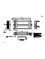
Page 21: ...Revision H August 19 1996 17 18 Figure 3 3 TN 200D Outline Dimensions ...

Page 22: ...Revision H August 19 1996 19 20 Figure 3 4 Typical Outline Drawing Dual Tray ...

Page 23: ...Revision H August 19 1996 21 22 Figure 3 5 Outline Drawing 3 Option ...

Page 24: ...Revision H August 19 1996 23 24 Figure 3 6 Interconnect Drawing TN 200D Without Glideslope ...

Page 25: ...Revision H August 19 1996 25 26 Figure 3 7 Interconnect Diagram TN 200D With Glideslope ...

Page 26: ... 88 After 5 seconds the displays will revert back to the last used frequencies Enter your desired frequency into the standby right hand window by turning the tune knob on the right hand side The faster this knob is rotated the more the frequency changes with each detent Clockwise tuning increases the frequency and counterclockwise tuning decreases the frequency At the upper and lower limits of the...

Page 27: ...ansfer will cause the unit to come up with 108 00 in the active display and the last transferred frequency in the standby display 4 7 TO PLACE FREQUENCIES IN MEMORY The TN 200D has a 10 user programmable memories To place frequencies in memory push the tune knob in In between the active and standby window O will be displayed After rotating the tune knob 1 detent from O an M will appear in the disp...

Page 28: ...8 MEMORY CHANNEL MODE Cycle power to the TN 200D after initialization push tune knob and rotate to 1m Press transfer button and 113 20 moves to the active window The previously displayed frequency moves to the standby window and 1m is cleared from the display To gain access to any channel simply push the tune button in rotate to desired channel press the transfer button and you are on your desired...

Page 29: ...id since it never changes Rotating the knob will now tune the MHz Scrolling past the end of the frequency range up or down will cause the frequency to wrap around to the other end of the range e g scrolling up past 117 wraps to 108 Pushing the knob again for approximately one third of a second will shift the cursor control from MHz to kHz Example lXX XX causing the MHz digits to light steady and t...

Page 30: ...e upwards through the memory positions Alternately holding the MEM button in will cause the unit to cycle through the memory positions at a rate of one position every one third of a second 4 7A TO PROGRAM NEW FREQUENCIES IN MEMORY Press MEM to select the desired memory position The M will illuminate between active and standby frequencies Tune the new frequency using either the continuous or cursor...

Page 31: ...irst press of the button the first click or first push of the tuning knob will restore the display with no changes e g the frequency will not transfer or change Once the display has relit the unit will function normally However pressing the MEM button will restore the display and recall the last Memory position to the standby display If no tuning control button MEM button or tuning knob is moved f...

Page 32: ...Revision H August 19 1996 33 Figure 4 2 TN 200D Front Panel Controls Mod 2 and above without glideslope Mod 3 and above with glideslope ...

Page 33: ...34 Revision H August 19 1996 THIS PAGE INTENTIONALLY LEFT BLANK ...

Page 34: ...d installed Also note your name address daytime telephone number and a description of the defect Ship the equipment UPS or equivalent You must prepay the shipping charges Ship to Trimble 2105 Donley Dr Austin TX 78758 512 432 0400 Phone 512 836 9413 FAX We will pay surface shipping charges to return the equipment to you What does your warranty not cover What does your warranty not cover What does ...

Page 35: ...36 Revision H August 19 1996 THIS PAGE INTENTIONALLY LEFT BLANK ...

Page 36: ...ision H August 19 1996 37 SECTION VI 6 INSTALLATION BULLETINS NOTES 6 1 INSTALLATION BULLETINS Place any installation bulletins after this page and record below DATE BULLETIN NUMBER DESCRIPTION ENTERED BY ...

Page 37: ...38 Revision H August 19 1996 6 2 INSTALLATION NOTES ...

Reviews: