


Revision H
August 19, 1996
2
1.3
SPECIFICATIONS
The following are pertinent specifications for the FCC type accepted Terra by Trimble TN
200D Navigational Receiver.
1.3.1
MECHANICAL
Mounting:
Panel mounted using mounting tray or 3" adapter as
provided
Overall Dimensions:
12.80" long, 3.125" wide, 1.625" high (32.50 cm long, 7.938
cm wide, 4.128 cm high)
Mounting Dimensions: 11.450" behind panel, 3.125' wide, 1.625" high (29.083 cm
behind panel, 7.938 cm wide, 4.128 cm high)
Panel Cutout:
3.03" x 1.54" (7.70cm x 3.91 cm)
Weight:
1.14 lbs (.52 kg) without G.S., 1.43 lbs (.649 kg) with G.S.
Connectors:
Antenna input; BNC Interconnect cable; 15 pin “D” type
1.3.2
POWER REQUIREMENTS
The Terra by Trimble TN 200D navigational receiver requires 13.75 VDC input
+10%, -20% at 0.6 amps under maximum load conditions.
1.3.3
ENVIRONMENTAL SPECIFICATIONS
Maximum Operating Conditions
Altitude:
To 30,000 ft (9,150 meters)
Humidity:
To 95% at 50oC (122oF)
Operating Temperature
Range:
-20oC (-4oF) to +55oC (+131oF)
Vibration:
0.5 G from 5 to 500 Hz
1.3.4
ELECTRICAL SPECIFICATIONS
VOR/LOC Receiver
Frequency Range:
108.00 to 117.95 MHz, 200 channels in 50 KHz steps
Sensitivity:
1.0uV for 6dB S+N/N ratio
Selectivity:
Typically 6dB at +17 KHz and 50dB at +50 KHz
VOR/LOC Composite In LOC mode factory preset to .18Vrms for Terra by
Trimble TRI NAV/C Indicator
Audio Output:
100mW into a 500 ohm load
Summary of Contents for TN 200D
Page 16: ...12 Revision H August 19 1996 THIS PAGE INTENTIONALLY LEFT BLANK ...
Page 18: ...14 Revision H August 19 1996 THIS PAGE INTENTIONALLY LEFT BLANK ...
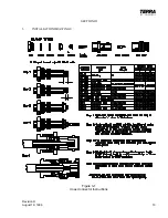
Page 19: ...Revision H August 19 1996 15 Figure 3 2 Coax Connector Instructions ...
Page 20: ...16 Revision H August 19 1996 THIS PAGE INTENTIONALLY LEFT BLANK ...
Page 21: ...Revision H August 19 1996 17 18 Figure 3 3 TN 200D Outline Dimensions ...
Page 22: ...Revision H August 19 1996 19 20 Figure 3 4 Typical Outline Drawing Dual Tray ...
Page 23: ...Revision H August 19 1996 21 22 Figure 3 5 Outline Drawing 3 Option ...
Page 24: ...Revision H August 19 1996 23 24 Figure 3 6 Interconnect Drawing TN 200D Without Glideslope ...
Page 25: ...Revision H August 19 1996 25 26 Figure 3 7 Interconnect Diagram TN 200D With Glideslope ...
Page 33: ...34 Revision H August 19 1996 THIS PAGE INTENTIONALLY LEFT BLANK ...
Page 35: ...36 Revision H August 19 1996 THIS PAGE INTENTIONALLY LEFT BLANK ...
Page 37: ...38 Revision H August 19 1996 6 2 INSTALLATION NOTES ...


