background image

Part No.  57.4400.9203                       GTH-4016SR • GTH-4018SR                  


93

March 2010

Section 7 • Schematics

REV A

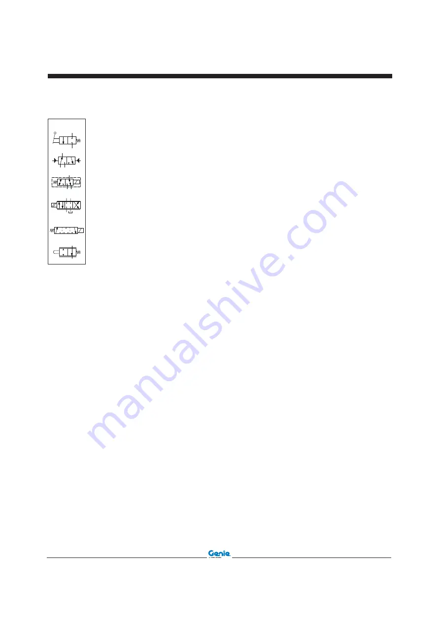
HYDRAULIC COMPONENT LEGEND

Two-position and two-way
distributor, with manual lever
control and spring return

DISTRIBUTION - SETTING
ELEMENTS

Three-way and two-position
distributor, with hydraulic control

Electro-hydraulic single-acting
servo valve

Distributor with mechanical
control and span proportional to
the action of the same control

Two-position, three-way
distributor, with representation
of transient connection during
passage phase

Two-position, three-way
distributor, with electro-magnetic
control and spring return

Summary of Contents for Genie GTH4016 SR

Page 1: ...English Service Manual GTH 4016 SR GTH 4018 SR Serial number range From serial n 20094 From serial n 19785 Part No 57 4400 9203 Rev A March 2010 ...

Page 2: ...hnical Publications Genie Industries has endeavored to deliver the highest degree of accuracy possible However continuous improvement of our products is a Genie policy Therefore product specifications are subject to change without notice Readers are encouraged to notify Genie of errors and send in suggestions for improvement All communications will be carefully considered for future printings of t...

Page 3: ... for instance engines pumps etc are located where originally applied by the manufacturers INTRODUCTION GTH 4016 P 10 20000 MODEL ENGINE TYPE YEAR OF MANUFACTURER SERIAL NUMBER Model Year Manufacturer Terexlift srl z i Buzzacchero 06019 Umbertide Italy MMMMMMMMMMMMMMMMMMMMMMMMMMMMMM AAAA MMMMMMMMMMMMMMMMMMMMMMMMMMMMMM AAAAAAAAAA AAAA AAAAAAAAA AAAAAAAAA AAAAAAAAA AAAAAAAAA AAAAAAAAA Country of Manu...

Page 4: ...iv GTH 4016SR GTH 4018SR Part No 57 4400 9203 March 2010 Intentionally blank page ...

Page 5: ...y of the hazards identified in the Operator s Manual are also safety hazards when maintenace and repair procedures are performed Do Not Perform Maintenace Unless You are trained and qualified to perform maintenace on this machine You read understand and obey manufacturer s instructions and safety rules employer s safety rules and worksite regulations applicable governmental regulations You have th...

Page 6: ...uretowearprotectiveeyewearand other protective clothing if the situation warrants it Be aware of potential crushing hazards such as moving parts free swinging or unsecured components when lifting or placing loads Always wear approved steel toed shoes Workplace Safety Be sure to keep sparks flames and lighted tobacco away from flammable and combustible materials like battery gases and engine fuels ...

Page 7: ...d Fitting Torque Specifications 11 Metric Fasteners Torque Charts 12 Section 3 Rev Scheduled Maintenance Procedures A Introduction 13 Pre delivery Preparation Report 15 Maintenance Inspection Report 17 A Checklist A Procedures A 1 Inspect the Manuals and Decals 18 A 2 Perform Pre operation Inspection 19 A 3 Perform Function Test 19 A 4 Machine Greasing 20 A 5 Epicyclic Reduction Gears Oil Level 21...

Page 8: ...vel 28 B 7 Block Valves 29 B 8 Tensioning The Boom Chains Only for GTH 4018 SR 29 A Checklist C Procedures C 1 Smoke From the Exaust Muffler 30 C 2 Change Engine Oil and Filter 30 C 3 Change Engine Air Outer Filter 31 C 4 Change Hydraulic Oil Filter 31 C 5 Clean Cabin Air Filter 32 A Checklist D Procedures D 1 Change Gear Box Oil 33 D 2 Change Oil in the Turntable Gear 33 D 3 Change Engine Air Inn...

Page 9: ...the Second Boom Section Extension Cylinder 48 1 10 How to Remove the Third Boom Section Extension Cylinder only for GTH 4016 SR 48 1 11 How to Remove the Fork Level Cylinder 49 1 12 How to Replace the Fork Level Cylinder Hoses only for GTH 4016 SR 50 A Operator s Compartment 2 1 How to Remove the Operator s Compartment 51 2 2 How to Remove the Steering Column 52 2 3 How to Test the Steering Column...

Page 10: ... Test the Outriggers Retracion Valve only for GTH 4018 SR 62 A Sensors 8 1 How to Remove the Boom Lenght and Angle Sensor 63 8 2 How to Test the Boom Lenght and Angle Sensor 63 8 3 How to Remove the Trasducer Pressure Switches 64 8 4 How to Test the Trasducer Pressure Switches 64 8 5 How to Test the Turret Proximity Switches 65 8 6 How to Test the Chassis Proximity Switches 65 8 7 How to Remove th...

Page 11: ...Troubleshoot the Mechanical Gear 86 Section 6 Rev Troubleshooting continued How to Troubleshoot the Jobsite Position 86 How to Troubleshoot the Outriggers Movements 87 How to Troubleshoot the Working Mode Selecting 88 Section 7 Rev Schematics A Introduction 89 Electrical Component Legend 90 Hydraulic Component Legend 92 Electrical Schematic 94 Hydraulic Schematic GTH 4016 SR 110 Hydraulic Schemati...

Page 12: ...xii GTH 4016SR GTH 4018SR Part No 57 4400 9203 March 2010 Intentionally blank page ...

Page 13: ...ar pump 4 having a displacement of 14 cm3 is installed on the PTO provided on the diesel engine distribution side The function of this pump is to provide hydraulic power to the braking systems service and parking and to the air conditioning system compressor optional When the work platform attachment optional is installed the additional emergency powerpack 5 is provided with the aim to allow the w...

Page 14: ...n charge pump The gearbox is mechanically linked through two distinct drive shafts to the front axle 20 and to the rear axle 21 both manufactured by Carraro so transmitting to the wheels the torque generated by the hydrostatic motor The front axle provided with an embedded steering cylinder 22 and articulation is rigidly secured on the front area of the undercarriage whilst the rear axle provided ...

Page 15: ... requested braking effect when the operator in the cabin pushes on the brake pedal When the selector valve 36 is energized the service brakes ports of the front axle receive a pressure of 10 bar which makes stronger the effect of the anti slipping device device which is installed inside the front axle This low pressure is generated by a pressure reducing valve 37 fed by the low pressure generated ...

Page 16: ...pacity of 0 5 liters and a nitrogen pre charge pressure of 35 bar is installed on the boom down hydraulic line to prevent any oscillation of the boom during the boom down movement The second section of the valve not pressure compensated controls the forks tilt up down functions and is linked to the forks tilt cylinder 48 through the double over center safety valve 49 On the same line of the forks ...

Page 17: ...it the loads against the stabilizers telescope lockout mechanisms in case of failure of the stabilizers telescope arm and rotating foot sequence control The scope of this additional circuit which is installed on the GTH 4018 SR only is to give the right functioning sequence to the stabilizers telescope arms and rotating feet since each of them is moved by the same cylinder In order to reduce the n...

Page 18: ...re 70 bar Pressure switch activating pressure 5 bar Pressure switch activating pressure 2 10 bar Hydraulically powered service emergency brakes pedal pump Air condition compressor hydraulic motor displacement 16 cc rev optional Tank lines collector 150 bar Pressure switch activating pressure 10 bar 20 R T N 30 bar Parking brake handle selector valve 190 bar 260 bar LS LS L R T P Steering rotating ...

Page 19: ...ressure 2 10 bar Hydraulically powered service emergency brakes pedal pump Air condition compressor hydraulic motor displacement 16 cc rev optional Tank lines collector 150 bar Pressure switch activating pressure 10 bar 20 R T N 30 bar Parking brake handle selector valve 190 bar 260 bar LS LS L R T P Steering rotating actuator displacement 200 cc rev Priority valve load sensing type T P A B C T P ...

Page 20: ...ire pressure 5 5 bar Tire ply rating 16 Wheel diameter 1104 mm Wheel width 460 mm Lug pattern 14x19 5 Lug nut torque dry 630 Nm Continuous improvement of our products is a Genie policy Product specifications are subject to change without notice Drive speed maximum GTH 4016SR GTH 4018SR 35 km h Towing capacity at dinamometer max load 7 000 kg without load 6 900 kg Lift capacity maximum GTH 4016SR G...

Page 21: ...mp Flow rate 2300 rpm 100 L min Pump pressure 193 bar measured at test port TP7 Continuous improvement of our products is a Genie policy Product specifications are subject to change without notice Main Valve System relief valve pressure maximum 280 bar Forks tilt section relief valves pressure max 320 bar Steering Circuit Steer relief valve pressure maximum 190 bar Braking Circuit Brake pump relie...

Page 22: ...el requirements refer to the engine Operation Manual on your machine Engine coolant Capacity 15 liters Alternator Output 100 A 12V DC Battery Type 12V DC Quantity 1 Cranking ampere 1200 EN Continuous improvement of our products is a Genie policy Product specifications are subject to change without notice Carraro 2632M FR Drive Axle GTH 4016SR and GTH 4018SR Steering Intergrated steer cylinder Join...

Page 23: ... on one of the flats of the hex nut and continue it on to the body hex fitting with a permanent ink marker a hydraulic hose b hex nut c reference mark d body hex fitting 3 Working clockwise on the body hex fitting make a second mark with a permanent ink marker to indicate the proper tightening position NOTICE The marks indicate that the correct tightening positions have been determined Use the sec...

Page 24: ...7 9 37 8 37 2 50 5 39 9 54 1 53 2 72 2 46 7 63 3 62 3 84 4 12 18 9 25 6 25 1 34 1 48 6 66 64 9 88 69 7 94 5 92 2 125 81 110 108 147 14 30 1 40 8 40 54 3 77 4 105 103 140 110 150 147 200 129 175 172 234 16 46 9 63 6 62 5 84 8 125 170 166 226 173 235 230 313 202 274 269 365 18 64 5 87 5 86 2 117 171 233 229 311 238 323 317 430 278 377 371 503 20 91 124 121 165 243 330 325 441 337 458 450 610 394 535...

Page 25: ...ked on a firm level surface Boom in the stowed p osition Key switch in the off position with the key removed Wheels chocked About This Section This section contains detailed procedures for each scheduled maintenance inspection Each procedure includes a description safety warnings and step by step instructions Symbols Legend Safety alert symbol used to alert personnel to potential personal injury h...

Page 26: ...duled inspection Make copies of the Pre delivery Preparation report to use for each inspection Store completed forms as required Maintenance Schedule There are five types of maintenance inspections that must be performed according to a schedule daily quarterly semi annually annually and two year The Scheduled Maintenance Procedures Section and the Maintenance Inspection Report have been divided in...

Page 27: ... R repaired Comments Fundamentals It is the responsibility of the dealer to perform the Pre delivery Preparation The Pre delivery Preparation is performed prior to each delivery The inspection is designed to discover if anything is apparently wrong with a machine before it is put into service A damaged or modified machine must never be used If damage or any variation from factory delivered conditi...

Page 28: ...March 2010 Section 3 Scheduled Maintenance Procedures 16 GTH 4016SR GTH 4018SR Part No 57 4400 9203 Intentionally blank page ...

Page 29: ... A 1 Manuals and decals A 2 Pre operation inspect A 3 Function tests A 4 Machine greasing A 5 Epicyclic reduction gears oil level A 6 Axles oil level A 7 Tyre inflation A 8 Engine oil level A 9 Engine cooling system A 10 Lighting system A 11 Clean engine air filters A 12 Safety devices Perform after 50 hours A 13 Emergency pump operation if presen A 14 Hydraulic oil level in the tank Checklist B R...

Page 30: ...ke sure that the operator s manual is present and complete in the storage container in the operator s compartment 2 Examine the pages of the manual to be sure that it is legible and in good condition Result The operator s manual is appropriate for the machine and it is legible and in good condition Result The operator s manual is not appropriate for the machine or it is not in good condition or is...

Page 31: ...rves to determine if routine maintenance procedures are required Complete information to perform this procedure is available in the appropriate operator s manual Refer to the Operator s Manual on your machine A 3 Perform Function Tests Completing the function tests is essential to safe machine operation Function tests are designed to discover any malfunctions before the machine is put into service...

Page 32: ...tings until the inner boom rollers are thoroughly lubricated 4 Lubricate the top boom tube wear pads NOTICE Do not lubricate the side wear pads at the boom rollers if equipped 5 Return the boom to the stowed position 6 Locate a grease fitting at one of the locations shown in the illustration 7 Pump grease into the fitting until the joint is thoroughly lubricated 8 Repeat this procedure beginning w...

Page 33: ...plug finds on the horizontal axis 2 Clean the plug all around then remove it and check if oil is level with the hole 3 If necessary add new oil through hole until it is level 4 Refit the plug A 6 Axles Oil Level 1 Stop the machine on a level ground and engage the parking brake 2 Loosen level plug and check if oil is level with the hole 3 If necessary top up through the same hole 4 Refit and tighte...

Page 34: ...The air pressure meets specification The tire is at the correctly filled level Result models with air filled tires The air pressure does not meet specification Add air until the air pressure meets specification 4 Repeat this procedure for each remaining tire A 8 Engine Oil Level NOTICE Engine specifications require that this procedure be performed daily Required maintenance procedures and addition...

Page 35: ...red maintenance procedures and additional engine information is available in the Perkins 1104D Operation and Maintenance Manual A 10 Lighting System 1 Stop the machine on a level ground and ensure the parking brake is engaged 2 Switch on the different traffic and work lights and check the inside cabin warning lights are on order 3 Leave the cabin and check if the lamps are working properly CHECKLI...

Page 36: ...hine shall not move 5 Outriggers Sensors Lower or raise all the outriggers The display of the moment limiter will change the scale of the admissible payloads accordingly 6 Pressure Switch On The Parking Brake Engage the parking brake and start the engine The warning light 41 should come on Attempt to move with the machine The machine must not move CHECKLIST A PROCEDURES A 11 Clean Engine Air Filte...

Page 37: ...mp works regularly A 14 Hydraulic Oil Level In The Tank WARNING Fine jets of hydraulic oil under pressure can penetrate the skin Do not use your fingers but a piece of cardboard to detect oil leaks 1 Check the hydraulic oil level visually through the special level fitted into the tank and placed on the cabin access steps 2 If necessary add new oil through the dedicated filler placed under the cove...

Page 38: ...level with the hole 4 When necessary add new oil through plug until it is level with the hole 5 Refit and tighten the plug B 2 Turntable Reduction Gear Oil Level 1 Stop the machine on a level ground and engage the parking brake 2 Clean level plug A all around 3 Loosen level plug A and check if oil is level with the hole 4 If necessary unscrew the filling plug B and pour new oil through the hole un...

Page 39: ...l wiring in good condition is essential to safe operation and good machine performance Failure to find and replace burnt chafed corroded or pinched wires could result in unsafe operating conditions and may cause component damage WARNING Electrocution hazard Contact with hot or live circuits could result in death or serious injury Remove all rings watches and other jewelry 1 Inspect the following a...

Page 40: ...t must never come in contact with the frame of the handler or electric electronic parts If the electrolyte comes in contact with these parts contact thenearestauthorisedassistance centre WARNING Do not add sulphuric acid add only distilled water B 5 Boom Sliding Pads Adjusting Any boom section is fitted with adjustable pads located on the four sides of the profile These pads are secured to both fi...

Page 41: ...res 3 Loosen the oil hoses to the cylinder of which you are checking the valve with caution 4 To check the efficiency of the block valves of the outriggers lower them to the ground and unload the weight of the tyres without raising them Loosen the cylinder hoses to check the efficiency of the valve During the check the oil will flow out of the hoses and the load shall remain blocked in position B ...

Page 42: ...he exhaust is normal repeat the check while accelerating the engine CAUTION Do this check outdoors or use an adequate smoke extraction system CAUTION In case of excess smoke strictly obey the instructions provided in the relevant Use and maintenance manual enclosed with the technical literature of the machine C 2 Change Engine Oil and Filter NOTICE Engine specifications require that this procedure...

Page 43: ... the parking brake 2 Place a container of suitable size under the filter to collect any oil leaks 3 Remove the filter cover to get access to the filter element A 4 Change the filter element then before fitting a new one thoroughly clean and grease both seat and gasket 5 Refit and tighten the filter cover NOTICE The hydraulic oil filter cartridge shall be replaced as soon as the relative warning li...

Page 44: ...ean Cabin Air Filter 1 Shut the engine down and engage the parking brake 2 Pull filter out of the housing accessible from the outside of the cab 3 Clean the filter bowl 4 Clean the filter cartridge by beating it against a piece of wood NOTICE Paper filters must never be cleaned using compressed air or washed with water and or solvents ...

Page 45: ...uction gear of the power divider Stop when oil is level with hole 6 Refit and tighten plug D 2 Change Oil in the Turntable Gear 1 Stop the machine on a level ground and engage the parking brake 2 Place a container of suitable size under drain plug C 3 Remove drain plug C and let oil flow out of the reduction gear 4 Unscrew the filling plug B 5 Clean level plug A all around 6 Loosen level plug A 7 ...

Page 46: ...ic Oil 1 Stop the machine on a level ground and make sure the parking brake is engaged 2 Release the pressure from the hydraulic circuit 3 Place a container of suitable size under the drain plug placed in the lower part of the reservoir and collect any oil leaks 4 Remove the drain plug and allow oil to flow out into the container 5 Refit the drain plug 6 Add new oil by making sure that it matches ...

Page 47: ... 3 Replace the cartridge D 6 Change Oil in the Axles 1 Place a container of suitable size under drain plug 2 To drain the oil remove one the two level plugs and the drain plug 3 Drain all oil 4 Clean the plug and tighten it to a 60Nm torque 5 Unscrew the oil fill plug and fill to the bottom of the level plug hole with the specified oil 6 Wait to allow the oil to flow through the axle Check oil lev...

Page 48: ...l end so that the plug is at the highest position pos A and partially unscrew to release possible pressure 2 Rotate the wheel end so that the plug is toward the ground pos B 3 Remove the plug and drain the oil 4 Rotate the wheel end so that the hole is in the position as shown in beside fig 5 Fill to the bottom of the fill plug hole with specified oil 6 Tighten the plug to a 60Nm torque CHECKLIST ...

Page 49: ...irst Required maintenance procedures and additional engine information is available in the Perkins 1104D Operation and Maintenance Manual E 2 Machine Structure NOTICE Terexlift require that this procedure be performed after 5 years or after 6000 hours whichever comes first Check the state of the structure paying attention to the welded supporting joints the boom pins the platform and all attachmen...

Page 50: ...38 GTH 4016SR GTH 4018SR Part No 57 4400 9203 March 2010 Section 3 Scheduled Maintenance Procedures REV A Intentionally blank page ...

Page 51: ...s in this section should only be performed by a trained service professional in a suitably equipped workshop Select the appropriate repair procedure after troubleshooting the problem Perform disassembly procedures to the point where repairs can be completed To re assemble perform the disassembly steps in reverse order Symbols Legend Safety alert symbol used to alert personnel to potential personal...

Page 52: ...rely 1 2 How to Remove the Lifting Fork Frame 1 With the boom in the stowed position attach a lifting strap from an overhead crane to the top of the lifting fork frame at the front of the boom Support the frame Do not apply any lifting pressure 2 If the machine is equipped with the lifting fork frame locking cylinder disconnect the locking cylinder hoses from the boom 3 Remove the screw securing t...

Page 53: ... harness to the boom iron hoses 3 Lift the boom up to when the rod end pivot pin is higher then the top of the cabin 4 Place a support under the lifting cylinder 5 Tag disconnect and plug the two hydraulic hoses from the main valve of the extension cylinder 6 Tag disconnect and plug the four hydraulic hoses from the main valve to the boom iron hoses two for tilting function and two for the attachm...

Page 54: ... disconnect and plug the four hydraulic hoses from bracket 3 4 Remove the two brackets 2 with the relative pulleys 5 Extend the boom for making accesible the inspection holes on inner section of boom 6 Inserting a spanner through the inspection holes remove the screws which fix the hoses holder block and disconnect the hydraulic hoses on the upper boom side 7 Completely retract the boom 8 Pull out...

Page 55: ... boom 10 Fit the chain bracket 9 with the relative chains 11 in the rear lower part of the third boom section 11 Fit the rear lateral paths of the third boom section 12 Slide in the third boom section into the second boom section pull the rope hooked up to the chains 3 and make them pass on the pulley 11 13 Fit the rear upper paths of the third boom section and all the ones of the second boom sect...

Page 56: ...eter Torque the chain tentionair to 50N m WARNING Bodily injury hazard This procedure requires specific repair skills lifting equipment and a suitable workshop Attempting this procedure without these skills and tools could result in death or serious injury and significant component damage Dealer service is strongly recommended NOTICE When removing a hose assembly or fitting the O ring on the fitti...

Page 57: ... machine and set the boom to horizontal position 2 Remove the pins 1 2 3 and 4 3 Slide out the third boom section extension cylinder 5 4 Remove the pin 6 and the forks frame 7 5 Remove the internal hydraulic hoses for extension fork levelling and attachment locking cylinder when present 6 Remove the front 11 and upper 12 lateral paths of the first boom section 7 Remove the rear lateral 13 and uppe...

Page 58: ... Fit the upper paths of the second boom section 12 10 In the first boom section fit all the paths front lateral 13 lower 14 upper 15 11 Insert the cylinder pin 16 12 Insert the extention cylinder pin 17 13 Insert the pins 18 19 21 the fork levelling cylinder 20 and the fork frame 22 14 Fit the hoses of the extension cylinder as follow slide in the hoses through the opening under the boom A push th...

Page 59: ...the up down controls of the bridge crane previously disconnect the rod of the fork balance cylinder BOOM COMPONENTS 8 Remove the screw fixing the pitching cylinder pin 9 Knock out and extract the pin using a plug of soft material aluminium copper wood etc 10 Fix the balance cylinder to the cabin with a sling and ensure it does not hinder the movement of the boom 11 Secure the raising cylinder to t...

Page 60: ...ect the two hydraulic hoses from the blocking valve then plug the disconnected connectors to prevent dust and impurities from entering the circuit 1 9 How to Remove the Second Boom Section Extension Cylinder WARNING Bodily injury hazard This procedure requires specific repair skills lifting equipment and a suitable workshop Attempting this procedure without these skills and tools could result in d...

Page 61: ...s 6 Disconnect three hydraulic hoses from the blocking valve then plug the disconnected connectors to prevent dust and impurities from entering the circuit 7 Drive out the lower pin 8 Unscrew and extract the screw fixing the pin 9 Knock out the pin using a plug of soft material aluminium copper wood etc and extract it through the hole on the frame 10 Remove the cylinder from the machine using the ...

Page 62: ...ting or refitting a flexible hose carefully clean the area all around 2 Blow some compressed air to remove any impurity 3 For an easier renewal of the hoses whose run is not clearly visible proceed as follows disconnect the hose to be replaced from both sides attach a cord to the side of the hose which reaches the boom tip disconnect the hose from the rear side of the boom remove the hose frome th...

Page 63: ...ler service is required 1 Cut the plastic fasteners fixing the electrical cables then disconnect all of the electrical wires 2 Disconnect the hydraulic lines of the power steering unit and of the heater 3 Disconnect the electrical and hydraulic connections of the brake pump 4 Disconnect the wire of the throttle pedal Remove the locking clip Remove the screws fixing the throttle rope 5 Disconnect t...

Page 64: ... 3 How to Test the Steering Column 1 Completly raise the boom 2 Apply the maintenance collar to the lifting cylinder 3 Disconnect the hose fitted in the CF position of the priority valve 4 Insert a T fitting between the priority valve and the hose and then apply a testing port 5 Install a 600 bar pressure gauge into the testing port 6 Start the engine completly turn the steering wheel and check th...

Page 65: ...ve the dashboard 4 Slip off the steering plug 5 Remove the upper plastic part of the steering selector 6 Remove all the screws that fix it in place 7 Slip off the selector OPERATOR S COMPARTMENT 2 5 How to Remove the Joystick 1 Locate and open the battery access door 2 Disconnect the battery from the machine WARNING Electrocution hazard Contact with electrically charged circuits could result in de...

Page 66: ...d Spraying hydraulic oil can penetrate and burn skin Loosen hydraulic connections very slowly to allow the oil pressure to dissipate gradually Do not allow oil to squirt or spray 2 Apply a testing port on the accumulator fitting 3 Riconnect the hose 4 Install a pressure gauge into testing port 5 Start the engine and allow the enigne to idle after warming the engine to operating temperature 6 Obser...

Page 67: ...4 Loosen all the clamps and pull out the hoses 5 Disconnect the electrical wire 6 Remove the electrical wire from bulb on the hydraulic filter 7 Place a container of suitable size under the hydraulic piping before disconnecting PROTECT THE ENVIRONMENT Used oils must be handled and disposed of according to local regulations Address to legally authorised centres 8 Disconnect all flexible hoses 9 Rem...

Page 68: ...ocedure with the engine off and cool 1 Completly open the engine hood 2 Remove the front cover of the engine housing 3 Remove the cover that is under engine 4 Using the cut off battery switch disconnect the battery 5 Remove the screws that fix the cut off battery switch support 6 Remove the hydrostatic transmission pump 7 Remove the two connectors 8 Tag disconnect and plug the hoses 9 Cap the hydr...

Page 69: ...g the brake pedal keep the machine stoped 7 Engage the forward or backward and check that the manometer on the port TP3 0 600psi reads a value of 50psi 8 If not set the valve under the pump 9 With the machine at the maximum rpm check that in the port TP3 the pressure gauge reads 450psi 10 If not set the valve on the right side of the pump 5 2 How to Remove the Boom Gear Function Pump 1 Closed the ...

Page 70: ...t must be 280 bar 6 If not set the pressure of the relief valve 5 4 How to Remove the Auxiliary Gear Pump 1 Closed the valve of the main hydraulic line It is behind the cabin steps 2 Tag the hoses 3 Remove the connectors 4 Remove the hoses WARNING Bodily injury hazard Spraying hydraulic oil can penetrate and burn skin Loosen hydraulic connections very slowly to allow the oil pressure to dissipate ...

Page 71: ... PUMPS 5 5 How to Test the Auxiliary Gear Pump 1 Insert the 0 60psi manometer in the TP4 port 2 Start the engine 3 Increase the engine up to 2000rpm 4 Close the valve placed near to the relief valve 5 Check the pressure in the manometer It must be 180psi 6 If not set the relief valve 7 Open the valve ...

Page 72: ...re to dissipate gradually Do not allow oil to squirt or spray 5 Cap the main valve holes and the hoses holes 6 Remove the main valve screws 7 Support and secure the main valve to a lifting device of suitable capacity Do not apply any lifting pressure 8 Raise the main valve and laying it on the floor 6 2 How to Test the Main Valve 1 Insert the 600 bar manometer in the TP1 port above the main valve ...

Page 73: ...s block holes and the hoses holes 5 Remove the screws that fix the valves block 6 Remove the outrigger valves block 7 2 How to Test the Pressure on the Outriggers Valves Block 1 Insert a 600 bar pressure gauge in the TP1 port of the main valve 2 Start the engine and lower the outriggers 3 Press the throttle pedal and make the engine increases up to maximum of rpm 4 Pushing the dedicated buttons ke...

Page 74: ...P5 port placed into the engine compartment 2 Start the engine and completly retract or extend the outriggers 3 Keep the outriggers in this position and check that the manometer reads 100 bar 4 If not set the valve placed in the front part of the chassis on a support in front of the slewing ring 5 Keeping the outriggers completly retracted or extended check that the manometer reads 100 bar OUTRIGGE...

Page 75: ...t the connector 2 Remove the retainer on the cable keeping a lot of attention 3 Remove the screws 4 Remove the boom lenght and angle sensor NOTICE After reinstalling the sensors follow the How to Set the Overload Warning System paragraph 8 2 How to Test the Boom Lenght and Angle Sensor 1 See paragraph Overload Warning System Fault Codes from point 5 to point 10 ...

Page 76: ...capacity 3 Remove the connector 4 Slowly remove the trasducer pressure switch WARNING Bodily injury hazard Spraying hydraulic oil can penetrate and burn skin Loosen hydraulic connections very slowly to allow the oil pressure to dissipate gradually Do not allow oil to squirt or spray 5 Cap the valve hoses SENSORS 8 4 How to Test the Trasducer Pressure Switches 1 See paragraph Overload Warning Syste...

Page 77: ... 8 6 How to Test the Chassis Proximity Switches 1 Remove the outriggers steel guards 2 Raise the outriggers and verify that the yellow LED placed on the proximity switch is on 3 Check that the machine can move 4 Lower the outriggers 5 Remove the turret locking pin 6 On the overload system display simultaneously press the two buttons PLUS and MINUS to access the Diagnostic Screen Pages 7 Using the ...

Page 78: ... A 8 7 How to Remove the Outriggers Load Pins 1 Lower the outriggers 2 Remove the connectors 3 Remove the screws 4 Using a teflon punch and a hammer pull out the load cell pin 5 Reassemble the load cell pin making sure the arrow is directed towards the external part of the machine SENSORS ...

Page 79: ...Insert the 600 bar pressure gauge in the TP6 port placed into the engine compartment 5 Keep doing the retraction movement and check the pressure it must be 150 bar 6 If not set the valve placed above the emergency pump 9 2 How to Test the Differential Lock Pressure Reducing Valve 1 In the valve placed on the front right side of the chassis install a 60 bar pressure gauge connected to the TP7 2 Sta...

Page 80: ... Engine RPM 1 Take a multimeter and set it on freq or Hrz 2 Connect the negative prod to the ground 3 Connect the positive prod to the W pin of the alternator 4 Start the engine 5 Using the manual accelerator increase the engine up to 1100rpm which on the multimeter corresponds to a reading of 0 40 MISCELLANEOUS ...

Page 81: ...s Start Read understand and obey the safety rules and operating instructions in the appropriate operator s manual on your machine Be sure that all necessary tools and parts are available and ready for use Read each procedure completely and adhere to the instructions Attempting shortcuts may produce hazardous conditions Unless otherwise specified perform each maintenance procedure with the machine ...

Page 82: ...enter in alarm mode and the writing err stab fw bw left righ open will appear on the bottom row of the main page If the load cell seized up the displayed warning will be err stab fw bw left righ vbat SETTINGS 10 Press button ARROW UP 11 Page 4 TILT SENSOR itrepresents inbit theelectroniclevellingsensor and it ranges between 2 5 When the value it registers is besides that range it is not possible t...

Page 83: ...er the winch rope x turret rotation enabling button when the value is 1 it indicates theenablingcontrolswitchplacedonthejoystick is active 24 Press button ARROW UP 25 Page 10 PRESSURE SENSORS itrepresentsthepressurevalue inbarandbit forthe pressureswitchesoftheliftingandlevellingcylinders Psp pressure switch value for lifting cylinder rod chamber psr pressure switch value for lifting cylinder pist...

Page 84: ...W UP or ARROW DOWN pushbuttons to select the language 15 ENTER 16 By using PLUS and MINUS pushbuttons select SAVE 17 ENTER 18 By using PLUS and MINUS pushbuttons select EXIT 19 ENTER 20 By using ARROW UP or ARROW DOWN pushbuttons select LENGHT 21 Completly retract the boom SETTINGS 22 ENTER 23 By using PLUS and MINUS pushbuttons select MIN 24 ENTER 25 By using PLUS and MINUS pushbuttons select SAV...

Page 85: ...e right month 58 ENTER 59 Blinking cursor pass to day field by using PLUS and MINUS pushbuttons set the right day 60 By using PLUS and MINUS pushbuttons select SAVE 61 ENTER 62 By using PLUS and MINUS pushbuttons select EXIT 63 ENTER 64 By using ARROW UP or ARROW DOWN pushbuttons select ENABLING IMPLEMENTS 65 ENTER 66 By using ARROW UP or ARROW DOWN pushbuttons select the attachment that have to b...

Page 86: ... to Open file reading parameter data Save file with parameter data only when parameters data have been read form display unit or when a file has been opened Read data from disply unit only when COM is selected serial adapter connected to PC and telehandler harness and telehandler has power switched on Write data to display unit only when COM is selected serial adapter connected to PC and telehandl...

Page 87: ... window will be displayed MI N MAX Ramp up Ramp down SETTINGS READ DATA is enabled only if COM port has been selected WRITE DATA is enabled only if COM port has been selected AND a FILE OPEN or a READ DATA are executed Descending menu selecting the place where function are operated Jobsite Platform Radio Short description of parameters ...

Page 88: ... 4018SR Part No 57 4400 9203 March 2010 Section 5 Settings REV A After opening a file or reading from display unit all function parameters available for the place where functions are operated will be displayed SETTINGS ...

Page 89: ...ers just written will be used when joystick pass through neutral Minimum MIN driving value is the command voltage that system uses when a function is operated and joystick is put just outside central neutral zone Maximum MAX driving value is the command voltage that system uses when a function is operated and joystick is put at its maximum stroke in one direction Ramp up parameter is the speed at ...

Page 90: ...V A Once clicked on Parameters Setting Slowing following window will be displayed READ DATA is enabled only if COM port has been selected WRITE DATA is enabled only if COM port has been selected AND a FILE OPEN or a READ DATA are executed Short description of parameters SETTINGS ...

Page 91: ...Part No 57 4400 9203 GTH 4016SR GTH 4018SR 79 March 2010 REV A Section 5 Settings After opening a file or reading from display unit all slowing parameters will be displayed SETTINGS ...

Page 92: ...80 GTH 4016SR GTH 4018SR Part No 57 4400 9203 March 2010 Section 5 Settings REV A Intentionally blank page ...

Page 93: ...are available and ready for use Be aware of the following hazards and follow generally accepted safe workshop practices DANGER Crushing hazard When testing or replacing any hydraulic component always support the structure and secure it from movement WARNING Electrocution hazard Contact with electrically charged circuits could result in death or serious injury Remove all rings watches and other jew...

Page 94: ...en calibrated or potentiometers are broken or there is some wire wrong connections 8 ERR ANG SENS 1 VBAT ERR ANG SENS 2 VBAT Angle sensor 1 or 2 signal is larger than maximum possible 4 5V or 920 BIT then telehandler can not work Sensor is broken or wire is connected to 5Vdc or 12Vdc voltage or sensor is not correctly connected to power supply 9 ERR ANG SENS 1 OPEN ERR ANG SENS 2 OPEN Angle sensor...

Page 95: ...witch is on Platform position but an implement is selected therefore telehandler can not work 15 ERR MODE SELECTOR Bothjobsitesignalandplatformsignalareat 12Vdc it is not a possible configuration then telehandler can not work The Platform Road Jobsite switch is brokenorsomewiringconnectioniswrong RedLED is switched on and buzzer is not activated ...

Page 96: ... some anomalies check the F13 fuse c Check the Jobsite Road Platform Selector connections d Check the joystick harness e If all these conditions are present replace the joystick Check the joystick screen page see How to Read the Overload Warning System Display paragraph point 21 If the values shown correspond to the relatives joystick movements verify the following items a Check the harnesses and ...

Page 97: ...wing items check fuse F20 10A integrity check there are 12V on pin A of the connectors X140 R front outrigger X143 L front outrigger X147 L rear outrigger X148 R rear outrigger If the outirigger is in storage position and the relative LED lights on on pin C there should be 12V If all listed above is confirmed check pin 1 R rear and pin 2 L rear of the connector X129 and pin 3 R front and pin 6 L f...

Page 98: ...firmed check the hydraulic system Keep particular attention for the overcharged pressure which must be about 25 bar How to Troubleshoot the Jobsite Position 1 Check if the Jobsite Road Platform selector is in Jobsite position 2 Check fuse F13 10A integrity 3 Check if there are 12V on connector X231 3 steering selection if not verify connector X180 2 if not verify connector X180 1 If not replace th...

Page 99: ...171 X172 X173 X174 Replace it if necessary 5 If all listed above is confirmed check pin 1 2 3 4 5 6 7 8 of the connector X201 6 If all listed above is confirmed check pin 9 10 11 12 29 38 39 40 of the connector X935 7 If all listed above is confirmed check pin 42 L front pin 19 R front pin 12 L rear and pin 16 R rear of the connector X935 If there aren t 12V the problem comes from the Software and...

Page 100: ...905 L rear X907 R rear d If all listed above is confirmed check pin 3 6 8 10 15 17 25 26 of the connector X130 e If all listed above is confirmed verify there are 12V on pin 38 of the connectors X935 L rear and pin 43 R rear pin 48 L front pin 19 R front of connector X934 f If all listed above is confirmed the problem comes from the Software and or Hardware Contact Genie Service If the value of on...

Page 101: ...y tools and test equipment are available and ready for use About This Section There are two groups of schematics in this section An illustration legend precedes each group of drawings Electrical Schematics WARNING Electrocution hazard Contact with electrically charged circuits could result in death or serious injury Remove all rings watches and other jewelry Hydraulic Schematics WARNING Bodily inj...

Page 102: ... RELAYS Relay Battery ACCUMULATORS Thermocouple Element Ring TERMINALS AND GROUNDS Ground Terminal Ground to frame Knot Protection ground Frame ground 2 Coil COILS Mechanical coupling coil Winding A C coil Coil with diode Winding with diode Connector CONNECTORS Auto transformer STATIC APPLICATIONS Transformer Motor DYNAMIC APPLICATIONS M G Generator M 3 As_3p_motor Rectifier ELECTRONIC PARTS Light...

Page 103: ... ELECTRICAL COMPONENT LEGEND Thermal CONTACTS Normally open NO Normally closed NC NO limit switch NC limit switch Contactor Magneto thermal closure Thermal closure Thermal opening Exchange NC proximity NO proximity NO mechanical NC mechanical Selector Selector2 Magneto thermal opening ...

Page 104: ...ical control with spring Mechanical control with roller Electro magnetic control with winding solendoid Control with electric motor M Direct pressure control Indirect piloted pressure control Control with electromagnet and piloted distributor Induction and return pipe Piloting pipe Blow by pipe MOTORS PUMP CYLINDERS COMMANDS AND CONTROLS PIPES AND CONNECTIONS Flexible hose Connecting point Pipe cr...

Page 105: ...TION SETTING ELEMENTS Three way and two position distributor with hydraulic control Electro hydraulic single acting servo valve Distributor with mechanical control and span proportional to the action of the same control Two position three way distributor with representation of transient connection during passage phase Two position three way distributor with electro magnetic control and spring retu...

Page 106: ...94 GTH 4016SR GTH 4018SR Part No 57 4400 9203 March 2010 Section 7 Schematics REV A Electrical Schematic GTH 4016SR and GTH 4018SR Page 1 of 16 ...

Page 107: ...Part No 57 4400 9203 GTH 4016SR GTH 4018SR 95 March 2010 Section 7 Schematics REV A Electrical Schematic GTH 4016SR and GTH 4018SR Page 2 of 16 ...

Page 108: ...96 GTH 4016SR GTH 4018SR Part No 57 4400 9203 March 2010 Section 7 Schematics REV A Electrical Schematic GTH 4016SR and GTH 4018SR Page 3 of 16 ...

Page 109: ...Part No 57 4400 9203 GTH 4016SR GTH 4018SR 97 March 2010 Section 7 Schematics REV A Electrical Schematic GTH 4016SR and GTH 4018SR Page 4 of 16 ...

Page 110: ...98 GTH 4016SR GTH 4018SR Part No 57 4400 9203 March 2010 Section 7 Schematics REV A Electrical Schematic GTH 4016SR and GTH 4018SR Page 5 of 16 ...

Page 111: ...Part No 57 4400 9203 GTH 4016SR GTH 4018SR 99 March 2010 Section 7 Schematics REV A Electrical Schematic GTH 4016SR and GTH 4018SR Page 6 of 16 ...

Page 112: ...100 GTH 4016SR GTH 4018SR Part No 57 4400 9203 March 2010 Section 7 Schematics REV A Electrical Schematic GTH 4016SR and GTH 4018SR Page 7 of 16 ...

Page 113: ...Part No 57 4400 9203 GTH 4016SR GTH 4018SR 101 March 2010 Section 7 Schematics REV A Electrical Schematic GTH 4016SR and GTH 4018SR Page 8 of 16 ...

Page 114: ...102 GTH 4016SR GTH 4018SR Part No 57 4400 9203 March 2010 Section 7 Schematics REV A Electrical Schematic GTH 4016SR and GTH 4018SR Page 9 of 16 ...

Page 115: ...Part No 57 4400 9203 GTH 4016SR GTH 4018SR 103 March 2010 Section 7 Schematics REV A Electrical Schematic GTH 4016SR and GTH 4018SR Page 10 of 16 ...

Page 116: ...104 GTH 4016SR GTH 4018SR Part No 57 4400 9203 March 2010 Section 7 Schematics REV A Electrical Schematic GTH 4016SR and GTH 4018SR Page 11 of 16 ...

Page 117: ...Part No 57 4400 9203 GTH 4016SR GTH 4018SR 105 March 2010 Section 7 Schematics REV A Electrical Schematic GTH 4016SR and GTH 4018SR Page 12 of 16 ...

Page 118: ...106 GTH 4016SR GTH 4018SR Part No 57 4400 9203 March 2010 Section 7 Schematics REV A Electrical Schematic GTH 4016SR and GTH 4018SR Page 13 of 16 ...

Page 119: ...Part No 57 4400 9203 GTH 4016SR GTH 4018SR 107 March 2010 Section 7 Schematics REV A Electrical Schematic GTH 4016SR and GTH 4018SR Page 14 of 16 ...

Page 120: ...108 GTH 4016SR GTH 4018SR Part No 57 4400 9203 March 2010 Section 7 Schematics REV A Electrical Schematic GTH 4016SR and GTH 4018SR Page 15 of 16 ...

Page 121: ...Part No 57 4400 9203 GTH 4016SR GTH 4018SR 109 March 2010 Section 7 Schematics REV A Electrical Schematic GTH 4016SR and GTH 4018SR Page 16 of 16 ...

Page 122: ...arge pressure 50 bar Capacity 1 5 litres precharge pressure 35 bar Pressure switch activating pressure 70 bar Pressure switch activating pressure 5 bar Pressure switch activating pressure 2 10 bar Hydraulically powered service emergency brakes pedal pump Air condition compressor hydraulic motor displacement 16 cc rev optional Tank lines collector 150 bar Pressure switch activating pressure 10 bar ...

Page 123: ...res precharge pressure 35 bar Pressure switch activating pressure 70 bar Pressure switch activating pressure 2 10 bar Hydraulically powered service emergency brakes pedal pump Air condition compressor hydraulic motor displacement 16 cc rev optional Tank lines collector 150 bar Pressure switch activating pressure 10 bar 20 R T N 30 bar Parking brake handle selector valve 190 bar 260 bar LS LS L R T...

Page 124: ......

Reviews: