TCW242-S_R1.0 – July 2021
Page 12
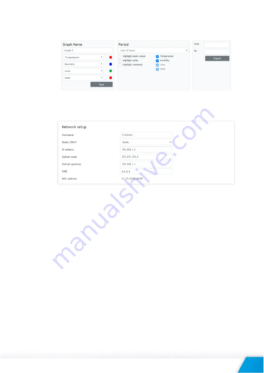
It is important to know that the information on graphs is static, it is not updated whit the newest
values. If you want to see the last information, the page should be reloaded. The information can
be exported in a CSV file.
8.2.
Setup
8.2.1.
Network
The network parameters can be set on this page.
The module supports static and dynamic IP addresses.
It is good practice to change the default IP address of the controller immediately after the first
power-on. This will avoid collisions if many devices are used on the same network.
It may be necessary to clear the arp cache, each time you connect a new device to the network.
This is done by typing arp -d in the command prompt window of the computer.
The “Hostname” is up to 15 characters. It is shown in the search results of the TCW discoverer.
It is recommended to use a public DNS server (8.8.8.8, 8.8.4.4, etc.) rather than the default
gateway.
8.2.2.
Modbus sensors
8.2.2.1.
Modbus RTU communication setup
Modbus RTU communication setup
This section allows you to set the communication parameters of the RS-485 interface – bit
rate, parity, and a number of stop bits. By default, the settings are 19200, even parity, and 1
stop bit. It is mandatory that all sensors on the bus use the same bit rate, parity, and number
of stop bits. Before adding any sensor to the interface its parameters should be set up
properly.
In the right part of the section, there is a tool that scans the bus and reports the number of
the found sensor together with their addresses. It is very useful at a time when you add new
sensors. It is recommended to use a small address segment to speed up the scan process.
Playing with “Scan time-out for sensor answer” it is possible to find this parameter for an
unknown sensor. The test starts with a large time-out (for example 500ms) and gradually
Summary of Contents for TCW242-S
Page 1: ......
Page 52: ...TCW242 S_R1 0 July 2021 Page 52 Appendix A Fig 1 Fig 2...


