background image

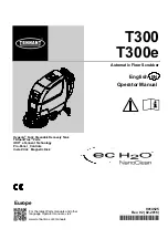
T300

T300e

9014525

Rev. 02 (02-2016)

Automatic Floor Scrubber

*9014525*

For the latest Parts manuals and other

language Operator manuals, visit:

www.tennantco.com/manuals

Hygenic

Fully Cleanable Recovery Tank

Tennant

True

Parts

IRIS

a Tennant Technology

Pro-Panel

t

Controls

Insta-Click

t

Magnetic Disk

English

EN

Operator Manual

Europe

Summary of Contents for IRIS T300

Page 1: ...525 For the latest Parts manuals and other language Operator manuals visit www tennantco com manuals Hygenic Fully Cleanable Recovery Tank TennantTrue Parts IRIS a Tennant Technology Pro Panelt Contro...

Page 2: ...EN ISO 3741 EN ISO 13059 EN ISO 3450 EN 60335 2 72 EN according to Annex II A of the Machinery Directive Ives Franssen Operation Manager TENNANT N V Industrielaan 6 5405 AB P O Box 6 5400 AA Uden The...

Page 3: ...MODEL WITH PRO PANEL CONTROLS 21 MACHINE OPERATION 25 PRE OPERATION CHECK LIST 25 OPERATING MACHINE 25 WHILE OPERATING MACHINE 27 EMERGENCY SHUT OFF BUTTON Drive models 27 BATTERY DISCHARGE INDICATOR...

Page 4: ...driver brush can be harmful to pacemaker wearers or medical implants This machine may be equipped with technology that automatically communicates over the cellular network If the machine will be opera...

Page 5: ...ncompatible battery chargers as this may damage battery packs and potentially cause a fire hazard Inspect charger cord regularly for damage Keep work area well ventilated Avoid contact with battery ac...

Page 6: ...battery cables before servicing machine Located on circuit board panel WARNING LABEL Spinning pad Keep hands away Located on disk scrub head model WARNING LABEL Magnetic field hazard Magnetic pad driv...

Page 7: ...ccessory rail s 9 On board battery charger cord hooks 10 Scrub head lift pedal 11 Squeegee foot pad 12 Squeegee assembly 13 Control handle 14 Control handle start bail 15 Speed control knob drive mode...

Page 8: ...it breaker Do not lift by accessory rails No step Dual down pressure T300e and T300 manual down pressure models No detergent ec H2O option Water temperature ec H2O option Battery charge Fast speed dri...

Page 9: ...a machine or charger fault is detected 2 Parking brake indicator Lights up when parking brake lever is engaged To turn off indicator disengage parking brake lever near left rear wheel 3 Battery disch...

Page 10: ...or quick operation The factory zone settings are configured with different solution flow rates down pressures and maximum scrub speeds T300 Model with Pro Panel Controls LCD Liquid Crystal Display 10...

Page 11: ...BLACK RED FIG 2 IMPORTANT Make sure that the machine s battery charger is properly set before charging See BATTERY CHARGER SETTINGS BATTERY PACK LIFT OUT TRAY Option Models equipped with the optional...

Page 12: ...or pad to use Contact a Tennant representative for specific recommendations Soft nylon bristle scrub brush White Recommended for cleaning coated floors without removing finish Cleans without scuffing...

Page 13: ...NSTALLING BRUSH PAD 3 Lug Disk T300e FOR SAFETY Before leaving or servicing machine stop on level surface turn off machine remove key and set parking brake if equipped 1 Step down on the scrub head li...

Page 14: ...as shown Figure 13 FIG 13 INSTALLING BRUSH PAD Insta Click Magnetic Disk FOR SAFETY Before leaving or servicing machine stop on level surface turn off machine remove key and set parking brake if equip...

Page 15: ...ng machine stop on level surface turn off machine remove key and set parking brake if equipped 1 Step down on the scrub head lift pedal to raise the scrub head off the floor Figure 19 FIG 19 2 Install...

Page 16: ...indicator Figure 27 ec H2O Scrubbing Only use cool clean water less than 21 C Do not use hot water or add conventional floor cleaning detergents An ec H2O system fault will occur if cleaning detergent...

Page 17: ...ank when refilling the solution tank 3 Adjust the mixing ratio knob according to the cleaning detergent s mixing instructions Figure 31 FIG 31 ec H2O NanoClean WATER CONDITIONING CARTRIDGE ec H2O mode...

Page 18: ...Option If model is equipped with the optional accessory clips the clips easily clip on and off the rails for additional accessory storage Figure 35 FIG 35 To install the accessory clips hook the clip...

Page 19: ...y as an alert that the dispensing is about to stop For continuous dispense press and hold the button for 2 seconds until LED turns solid green Press button at anytime to turn off The icon will blink b...

Page 20: ...flow setting No LED No flow One LED Low flow two LED s Medium flow three LED s High flow FIG 45 4 Models equipped with Severe Environment button option Press Severe Environment button one time to disp...

Page 21: ...TH PRO PANEL CONTROLS There are two types of user modes that will interface with the operator home screen Operator Mode Capable of machine operation with permissions and restrictions controlled by the...

Page 22: ...crease down pressure Press the symbol to decrease the down pressure FIG 54 4 Press the solution flow icon to display the solution flow scale Figure 55 Press the symbol to increase solution flow Press...

Page 23: ...press and hold the zone number button until it prompts you to name the new zone setting Select yes to enter a new name Figure 60 By selecting no the preset name will be removed NOTE Only the superviso...

Page 24: ...n will flash yellow or red when a machine fault is detected Figure 65 FIG 65 In conjunction with a flashing service indicator icon the following fault screens will automatically pop up to indicate the...

Page 25: ...The ec H2O system will automatically turn on at start up To turn off the ec H2O system press the ec H2O switch located below the key switch Figure 70 ATTENTION During first time use and after replaci...

Page 26: ...g press the solution flow button located on the ec H2O module Figure 76 One LED low two LED s medium and three LED s high FIG 76 10 T300e model To adjust the solution flow rate when conventional scrub...

Page 27: ...and floor mounted fixtures such as pedestal sinks and other breakable items Keep the metal scrub head edge away to avoid possible damage Tile Cove FIG 79 9 When leaving the machine unattended remove t...

Page 28: ...0e FOR SAFETY When servicing machine all repairs must be performed by trained personnel HOUR METER The hour meter records the number of hours the machine has been operated Use the hour meter to perfor...

Page 29: ...achine stop on level surface turn off machine remove key and set parking brake if equipped 2 To drain remaining water from solution tank pull the solution hose from the accessory rail Figure 88 FIG 88...

Page 30: ...S S 0x0301 Solution valve wiring connector or control board problem Check connections Contact service S S 0x0303 Solution valve over current Contact service S S 0x0307 Solution valve control board fa...

Page 31: ...ent Contact service S S 0x0606 Severe environment detergent pump shorted fault Contact service S S 0x0106 Brush motor shorted fault Contact service S S 0xF103 0xFF20 0x0704 Charger communication fault...

Page 32: ...ec H2O system breaker tripped ec H2O pump breaker tripped Reset circuit breaker If trip repeats contact service ecH2O indicator solid red 0x0716 0x0727 0x0741 0x0746 ec H2O pump shorted fault ec H2O c...

Page 33: ...crub head skirt Check for damage and wear Weekly O 7 Battery cells Check electrolyte level O 6 Squeegee assembly drip trap reservoir Check clean 50 Hours O 2 Cylindrical brushes Rotate brushes Check f...

Page 34: ...ed All repairs must be performed by trained personnel AFTER DAILY USE 1 Drain and rinse out the recovery tank Figure 91 See DRAINING TANKS FIG 91 2 Remove the debris tray and empty Figure 92 FIG 92 3...

Page 35: ...purpose cleaner and damp cloth Figure 100 FIG 100 10 Cylindrical scrub head Remove and clean debris trough Figure 101 FIG 101 11 Severe environment option Refill the severe environment tank with a rec...

Page 36: ...spect and clean the seal on the recovery tank lid Figure 109 Replace seal if damaged FIG 109 AFTER EVERY 100 HOURS OF USE If machine is equipped with the optional battery watering system check the wat...

Page 37: ...for a minimum of 15 minutes S Do not leave the batteries partially discharged for long period of time S Only charge the batteries in a well ventilated area to prevent gas build up Charge batteries in...

Page 38: ...is not equipped with charger FOR SAFETY The use of incompatible battery chargers may damage battery packs and potentially cause a fire hazard IMPORTANT NOTICE The battery charger is set to charge the...

Page 39: ...ply cord and wrap cord around the cord hooks Figure 118 For models equipped with an off board charger always disconnect the AC power supply cord first before disconnecting charger from machine FIG 118...

Page 40: ...nnenschein 80 150 AH The factory setting dial position 0 is pre programmed to accommodate the battery type supplied with new machine After the dial is changed from the factory setting it should not be...

Page 41: ...n 1 Remove the squeegee assembly from the machine 2 Fully loosen the two outside knobs on squeegee assembly This will separate the spring loaded blade retainer from squeegee frame Figure 127 To loosen...

Page 42: ...g cartridge Figure 131 Drain recovery tank before lifting tank FIG 131 3 Disconnect the two hose connectors from the top of the cartridge by pressing the gray collars inward and pulling the connectors...

Page 43: ...of time 1 Charge the batteries before storing machine to prolong the life of the batteries Recharge batteries once a month 2 Disconnect batteries before storing 3 Drain and rinse recovery tank and sol...

Page 44: ...SERVICE INDICATOR CODES Faulty charger Replace charger Machine will not propel Drive Model Propel fault has been detected See SERVICE INDICATOR CODES Circuit breaker tripped Reset circuit breaker Fau...

Page 45: ...ot completely closed Check lid for obstructions Defective seals on recovery tank lid Replaced seal Little or no solution flow Empty solution tank Refill solution tank Low solution flow rate set Increa...

Page 46: ...ncline for transporting 21 maximum Ramp incline for loading empty tanks 21 maximum Solution flow rate T300e 1 9 L min maximum Solution flow rate T300 Low 57 L min Med 1 3 L min High 1 9 L min ec H2O s...

Page 47: ...e T300e 1 9 L min maximum Solution flow rate T300 Low 57 L min Med 1 3 L min High 1 9 L min Low 57 L min Med 1 0 L min High 1 3 L min Low 57 L min Med 1 3 L min High 1 9 L min ec H2O solution flow rat...

Page 48: ...SPECIFICATIONS 48 Tennant T300e T300 03 2015 MACHINE DIMENSIONS 1095 mm 772 mm SINGLE DISK MODEL 1302 mm 43 cm Model 1372 mm 50 cm Model 508 mm 43 cm Model 559 mm 50 cm Model...

Page 49: ...SPECIFICATIONS Tennant T300e T300 03 2015 49 1095 mm 772 mm DUAL DISK MODEL 1314 mm 660 mm...

Page 50: ...SPECIFICATIONS 50 Tennant T300e T300 03 2015 1095 mm 772 mm CYLINDRICAL BRUSH MODEL 1283 mm 635 mm...

Page 51: ...SPECIFICATIONS Tennant T300e T300 03 2015 51 1095 mm 772 mm ORBITAL PAD MODEL 1245 mm 521 mm...

Page 52: ...SPECIFICATIONS 52 Tennant T300e T300 03 2015...

Page 53: ...a level surface and turn the key to off O position 2 Press and hold the Down Pressure button while turning the key on Release button when the far right battery discharge indicator LED turns on Figure...

Page 54: ...e factory assigned supervisor login number or your saved personalized supervisor login number to access the operator home screen 2 Press the settings button located on the home screen Figure 141 FIG 1...

Page 55: ...be any combination of numbers ranging from 3 to 8 digits long FIG 148 6 Now select the controls that the new user should have access to use Figure 149 Green represents unlocked controls and gray repr...

Page 56: ...profiles Figure 154 For example to edit any user profile settings including the factory assigned default supervisor login number press the Edit Profile button FIG 154 To change the factory assigned de...

Page 57: ...sired default user by pressing the Operator or Supervisor button Figure 159 FIG 159 d Select a pre assigned user profile In this example operator profile JOHN is selected Figure 160 Turn the key off t...

Reviews: