DESCRIPTION
2.6 Fast
Cooldown
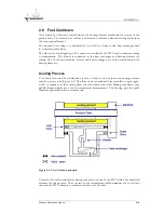
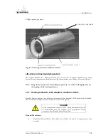
Air is forced by a blower to travel between the heating element mantle and the outside of the
process tube. The direction of airflow is alternated to achieve balanced cooling faster than
the conventional furnace.
The air used for cooling is re-circulated. It is cooled by a water-cooled heat exchanger built
in, in the furnace cabinet.
The blower is a centrifugal type. The speed is controlled by the DTC and is varied according
to requirements. The blower is connected to the heat exchanger and heating element via
tubing. The Cool down modules (blower and heat exchanger) are both situated behind the
heating elements.
Cooling Process
Cool down is assisted by conditioned air that is forced to flow between the heating element
and the process tube (Figure 2-4). The flow of air is periodically reversed left-to-right; right-
to-left to equalize out the cooling effect over the whole wafer load. During cool-down, only
paddle thermocouples are used for temperature measurement. The flowing past the spike
thermocouples makes their use inaccurate.
Figure 2-4 Fast Cooldown principle
Control of the valves and blower during cool-down is done by the DTC which has dedicated
software for the purpose. The cool rate in the temperature table determines the cool down
time and the DTC attempts to maintain this rate over all zones.
F
URNACE
R
EFERENCE
M
ANUAL
2-6


