Temposonics
®
GB-Series SSI
Operation Manual
5. peration
5. Getting started
7KHVHQVRULVIDFWRU\VHWWRLWVRUGHUVL]HVDQGDGMXVWHGLHWKHGLV
-
WDQFHEHWZHHQPDJQHWDQGĠDQJHLVVSHFLğHGLQUHVROXWLRQVWHSV
([DPSOH66,YDOXHDWWKHVWDUWRIPHDVXULQJUDQJHPPZLWK
a resolution of 1 m
NOTICE
If necessary, the SSI sensors can be re-adjusted using
the service tool described below.
5.2
3URJUDPPLQJDQGFRQğJXUDWLRQ
SSI interface
The interface of Temposonics
®
position sensors corresponds to SSI
industry standard for absolute encoders. Its displacement value is
HQFRGHGLQDELWELQDU\RUJUD\IRUPDWDQGWUDQVPLWWHG56
FRPSDWLEOHYLDZLUHVŋLQGHSHQGHQWRIGDWDZLGWKRIWKHFRGHUHVR
-
OXWLRQ
The absolute, parallel position data is continually updated by the
sensor and converted by the shift-register into a serial bit stream
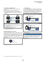
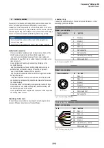
)LJ
Fig. 23:
6FKHPDWLFFRQQHFWLRQ
Fig. 24:
,QSXWZLULQJFORFNFORFN
ũ
Fig. 25:
7LPLQJGLDJUDP
TS Sensors programming tools
Temposonics
®
SRVLWLRQVHQVRUVFDQEHDGDSWHGWRPRGLğHG
measurement tasks very easily via the connecting leads without
opening the sensor. For this, the MTS Sensors programming kit is
DYDLODEOHVHHSDJH
7KLVFKDSWHUGHVFULEHVŃSURJUDPPLQJDQGFRQğJXUDWLRQńRIWKH
*%66,VHQVRUYLDFDEOHFRQQHFWLRQ
Ń3URJUDPPLQJDQGFRQğJXUDWLRQńYLD%OXHWRRWK
®
connection are
explained in document 551649.
NOTICE
ser e during commissioning
1. efore initial switch-on, check carefully if the sensor has been
connected correctly.
2. Position the magnet in the measuring range of the sensor
GXULQJğUVWFRPPLVVLRQLQJDQGDIWHUUHSODFHPHQWRIWKHPDJQHW
(QVXUHWKDWWKHVHQVRUFRQWUROV\VWHPFDQQRWUHDFWLQDQ
uncontrolled way when switching on.
(QVXUHWKDWWKHVHQVRULVUHDG\DQGLQRSHUDWLRQPRGHDIWHU
switching on
.
5. Check the pre-set span start and end values of the measuring
UDQJH)LJDQGFRUUHFWWKHPYLDWKHFXVWRPHUłVFRQWURO
system if necessary, or via the MTS Sensors service tool.
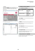
The operation of the service tool is described in detail on the
following pages.
Sensor input
91 Ω
7 mA
Clock (+)
100 Ω
LED
100 Ω
Clock (−)
91 Ω
Optocoupler
2 V
1 nF
1 nF
Clock (+)
Data (+)
MSB
LSB
Clock interval min. 16 μs
Logic diagram
Sensor
Controller
Clock (+)
Clock (−)
Optocoupler
Driver
Data (+)
Data (−)
+24 VDC
0 V
ASIC for parallel and
absolute position data
Microprocessor system
position value = 24 / 25 bit
binar
y or gray
Shift register
parallel serial converter

