background image

21

Temposonics

®  

GB-Series SSI

Operation Manual

easurement

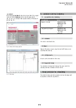
After clicking the 

Start Read

 button the current position of the magnet 

is shown. Click the 

Stop Read

 button to stop the measurement  

)LJ7KH

ie

 button provides a graphic display of the magnet s 

SRVLWLRQ)LJ

Fig. 31: 

'LVSOD\RIFXUUHQWPDJQHWSRVLWLRQ

Fig. 32: 

'DWDGLVSOD\

6.  aintenanc e and trou leshooting

6.   rror conditions, trou leshooting

6.2  aintenance

The sensor is maintenance-free. 

6.3 Repair

5HSDLUVRIWKHVHQVRUPD\RQO\EHSHUIRUPHGE\0766HQVRUVRUDQ
H[SOLFLWO\DXWKRUL]HGERG\

6.4  ist of spare parts

1RVSDUHSDUWVDUHDYDLODEOHIRUWKLVVHQVRU

6.5 Transport and storage

The conditions of transport and storage of the sensor match the
operating conditions mentioned in this document.

.  Remo al from ser ice   dismantling

The product contains electronic components and must be disposed of 
in accordance with the local regulations.

rror condition

Status

Magnet not detected

efault error  alue  
dapted error  alue  

16777215

VHH)LJ

rong quantity of magnets

efault error  alue  
dapted error  alue

16777215

VHH)LJ

Summary of Contents for GB Series

Page 1: ...Operation Manual GB Series SSI Magnetostriktive Lineare Positionssensoren ...

Page 2: ...onality and system design 7 4 2 Styles and installation of Temposonics GB J GB K GB N GB S 8 4 3 Styles and installation of Temposonics GB M GB T GB B 10 4 4 Magnet installation 12 4 5 Change orientation of sensor electronics housing 14 4 6 Replacement of base unit 14 4 7 Electrical connection 15 4 8 Frequently ordered accessories 16 5 Operation 18 5 1 Getting started 18 5 2 Programming and configu...

Page 3: ...or other electronic control unit Before starting the operation of Temposonics position sensors read this documentation thoroughly and follow the safety information Keep the manual for future reference Symbol Meaning This symbol is used to point to situations that may lead to material damage but not to personal injury NOTICE 2 2 Forseeable misuse Do not step on the sensor The sensor might be damage...

Page 4: ...ocumenta tion of the checks 7 HIRUH DSSO LQJ SRZHU HQVXUH WKDW QRERG łV VDIHW LV MHRSDUGL HG by starting machines 2 4 Safety instructions for use in explosion hazardous areas 7KH VHQVRU LV QRW VXLWDEOH IRU RSHUDWLRQ LQ H SORVLRQ KD DUGRXV DUHDV 2 See also applicable MTS Sensors terms of sales and delivery on www mtssensors com 2 5 Warranty MTS Sensors grants a warranty period for the Temposonics p...

Page 5: ... LQ IHHW LI XVLQJ 86 FXVWRPDU stroke length 1 2 3 4 5 6 7 9 1 11 12 13 14 15 16 17 19 2 21 G B S a c d e f g h c Stro e length 25 325 mm Ľ LQ Standard stro e length mm rdering steps 25 5 mm 5 mm 5 75 mm 1 mm 75 1 mm 25 mm 1 25 mm 5 mm 25 325 mm 1 mm Standard stro e length in rdering steps 1 2 in 2 in 2 3 in 5 in 3 4 in 1 in 4 1 in 2 in Ľ LQ 4 in esign ZLWK WKUHDGHG ĠDQJH B DVH XQLW IRU WKUHDGHG ĠD...

Page 6: ...utput format ox no 5 B inary G UD Resolution ox no 6 5 mm 2 1 mm 3 5 mm 4 1 mm 5 2 mm iltering performance ox no 1R ğOWHU 2 YHUDJH ğOWHU 3 YHUDJH ğOWHU 4 YHUDJH ğOWHU erformance ox no Measuring direction forward asynchronous measurement Measuring direction reverse asynchronous measurement 2 Measuring direction forward synchronous measurement 3 Measuring direction reverse synchronous measurement ...

Page 7: ...RQDO VWUDLQ SXOVH WKDW SURSDJDWHV WKH length of the waveguide hen the ultrasonic wave reaches the end of the waveguide it is converted into an electrical signal Since the speed of the ultrasonic wave in the waveguide is precisely known the time required to receive the return signal can be converted into a linear position measurement with both high accuracy and repeatability odular mechanical and e...

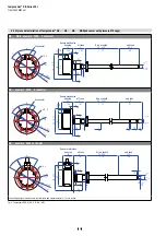
Page 8: ...nics housing 34 1 34 GB example With 6 connector agnet 79 3 11 1 f7 11 3 44 51 2 1 6 24 25 1 1 39 3 12 22 7 15 59 12 1 5 4 M6 3 64 2 52 6 5 26 6 3 53 2 9 Sensor electronics housing 34 1 34 Stro e length 25 325 1 12 ull zone 4 1 57 ead zone 7 5 3 1 1 32 4 1 16 6 connector GB example With ca le out let agnet 25 1 79 3 11 51 2 1 6 24 M6 3 6 5 26 64 2 52 6 3 53 2 9 Stro e length 25 325 1 12 ull zone 4...

Page 9: ...SHQGHQW RI WKH K GUDXOLF ĠXLG The pressure resistant sensor rod is installed into a bore in the piston rod ydraulics sealing 6HDO WKH ĠDQJH FRQWDFW VXUIDFH YLD 2 ULQJ LQ WKH XQGHUFXW DV VKRZQ LQ Fig 6 RU SUHVVXUH ğW ĠDQJH I 1 6 2 ULQJ ū PP LQ SDUW QR RU SUHVVXUH ğW ĠDQJH I 2 5LQJ ū PP LQ SDUW QR Fig 6 Sealing 1RWH WKH IDVWHQLQJ WRUTXH RI PDFKLQH VFUHZV RI 1P 6HDW WKH ĠDQJH FRQWDFW VXUIDFH FRPSOHWH...

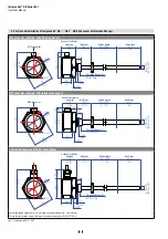
Page 10: ... M16 connector Threaded flange T 16 UNF 3A Ø 54 Ø 2 13 M4 3 55 2 17 Stroke length 25 3250 1 128 Dead zone 63 5 2 5 Magnet 2 5 0 1 Ø 25 4 Ø 1 A F 55 DEOH RXWOHW DPSOH LWK ĠDW IDFHG ĠDQJH Threaded flange M M18 1 5 6g 55 2 17 M4 3 77 4 3 05 Ø 54 Ø 2 13 54 5 2 15 22 9 0 9 25 1 4 1 0 16 14 0 55 Null zone 40 1 57 Stroke length 25 3250 1 128 Dead zone 63 5 2 5 Ø 10 0 13 Ø 0 39 0 01 Sensor electronics housi...

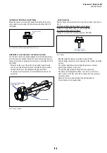
Page 11: ...screws It is the only part that needs to be replaced if servicing is required i e the hydraulic circuit remains closed For more information see chapter Ń 5HSODFHPHQW RI EDVH XQLWń RQ SDJH Fig 10 6HQVRU LQ F OLQGHU ydraulics sealing 7KHUH DUH WZR ZD V IRU VHDOLQJ WKH ĠDQJH FRQWDFW VXUIDFH LJ 1 VHDOLQJ E XVLQJ DQ 2 ULQJ H J ū PP ū LQ in a cylinder end cap groove 2 A sealing via an O ring in the unde...

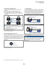
Page 12: ...or rod Alignment errors are compensated via the air gap 3HUPLVVLEOH VXUIDFH SUHVVXUH 0D 1 PP2 DVWHQLQJ WRUTXH IRU 0 VFUHZV 1P XVH ZDVKHU LI QHFHVVDU Minimum distance between position magnet and any magnetic PDWHULDO KDV WR EH PP LQ LJ If no other option exists and magnetic material is used observe the VSHFLğHG GLPHQVLRQV LJ Fig 13 7 SLFDO XVH RI ULQJ PDJQHWV DQG 8 PDJQHWV NOTICE Mount ring magnets...

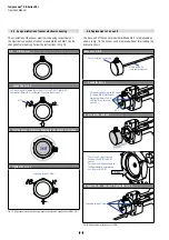
Page 13: ...QJWK XVHIXO HOHFWULFDO VWURNH ZLWK LWV VWDUW DQG HQG SRVLWLRQ LV DGMXVWHG GXULQJ ğQDO LQVSHFWLRQ DQG WHVWLQJ LJ To ensure that the entire measuring range can be used electrically the SRVLWLRQ PDJQHW PXVW EH PRXQWHG PHFKDQLFDOO DV IROORZV 6HULHV ZLWK SUHVVXUH ğW ĠDQJH ZLWK ULQJ 8 PDJQHW 40 Stroke length 63 5 Reference edge of mounting Start position 6HULHV ZLWK WKUHDGHG ĠDQJH ZLWK ULQJ 8 PDJQHW 40 ...

Page 14: ...ng as shown in the figure before inserting the new base unit GB B O ring 3 Insert the ne ase unit Tighten the scre s Fastening torque 1 6 Nm 4 5 hange orientation of sensor electronics housing The orientation of the sensor electronics housing respectively of WKH HOHFWULFDO FRQQHFWLRQ RI VHQVRU PRGHOV 0 DQG 7 FDQ EH FKDQJHG DIWHU PRXQWLQJ ROORZ WKH LQVWUXFWLRQV LQ LJ LJ OLJQ VHQVRU HOHFWURQLFV KRXVL...

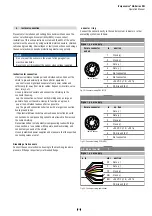
Page 15: ... potential differences between machine and electronics earth FRQQHFWLRQV QR FRPSHQVDWLQJ FXUUHQWV DUH DOORZHG WR ĠRZ DFURVV the cable shielding 5HFRPPHQGDWLRQ QVWDOO SRWHQWLDO FRPSHQVDWLQJ OHDGV ZLWK ODUJH cross section or use cables with separate double shielding and connect only one end of the shield 8VH RQO VWDELOL HG SRZHU VXSSOLHV DQG PDNH VXUH WKDW WKH VSHFLğHG connecting values are met Fig ...

Page 16: ... Ľ Ź osition magnet rings Bac up ring Ø 4 5 Ø 0 18 Ø 63 5 Ø 2 5 Ø 42 Ø 1 65 Ø 16 Ø 0 63 97 3 0 9 5 0 37 15 59 2 Ø 17 Ø 0 67 Ø 2 Ø 0 07 Ø 18 Ø 0 71 1 4 0 05 1 5 0 06 magnet 63 5 art no 2 553 2 ULQJ IRU SUHVVXUH ğ W Ġ DQJH PP art no 56 53 2 ULQJ IRU SUHVVXUH ğ W Ġ DQJH PP art no 56 43 DFN XS ULQJ IRU SUHVVXUH ğ W Ġ DQJH PP art no 56 5 0DWHULDO 3 PDJQHWV FRPSRXQG ğ OOHG HLJKW Approx 26 g 6XUIDFH SUHV...

Page 17: ...RWHFWLRQ 3 3 FRUUHFWO ğ WWHG DVWHQLQJ WRUTXH 1P 0DWHULDO LQF QLFNHO SODWHG 7HUPLQDWLRQ 6ROGHU RQWDFW LQVHUW 6LOYHU SODWHG DEOH Ľ PP Ľ LQ LUH PPš 2SHUDWLQJ WHPSHUDWXUH ũ Ľ Ź ũ Ľ Ź QJUHVV SURWHFWLRQ 3 FRUUHFWO ğ WWHG DVWHQLQJ WRUTXH 1P a les rogramming tool R ca le art no 53 52 7HĠ RQ ca le art no 53 2 Silicone ca le art no 53 3 rogramming it art no 254 5 0DWHULDO 385 MDFNHW RUDQJH HDWXUHV 7ZLVWHG S...

Page 18: ...sensor For this the MTS Sensors programming kit is DYDLODEOH VHH SDJH 7KLV FKDSWHU GHVFULEHV ŃSURJUDPPLQJ DQG FRQğJXUDWLRQń RI WKH 66 VHQVRU YLD FDEOH FRQQHFWLRQ Ń3URJUDPPLQJ DQG FRQğJXUDWLRQń YLD OXHWRRWK connection are explained in document 551649 NOTICE ser e during commissioning 1 efore initial switch on check carefully if the sensor has been connected correctly 2 Position the magnet in the me...

Page 19: ...RJUDPPHU Step 2 Instal l soft are 6WHS 6WDUW SURJUDP 6WHS RQQHFW 3 SURJUDPPHU 6WHS QVWDOO VRIWZDUH Step 3 Start program Programming kit part no 254 59 The PC programmer is a hardware converter between sensor and serial PC interface It can be used for adjusting sensor parameters via computer and the MTS Sensors programming software The software for reading and adjusting the sensors requires a indow...

Page 20: ...H VHWWLQJV DV 0 ğOH 3 Restore actory Settings 5HVWRUHV DQG VDYHV WKH VHQVRUłV IDFWRU settings 4 lose ORVHV WKH VRIWZDUH DSSOLFDWLRQ ZLWKRXW VDYLQJ DQ parameters e ice Settings 7KH IROORZLQJ SDUDPHWHUV FDQ EH PRGLğHG 66 6HWWLQJV LJ RUPDW Binary Gray DWD HQJWK 24 its 25 its 5HVROXWLRQ 5 m m 2 m 5 m m 0RGH synchron In asynchronous mode the sensor starts measuring and provides the position independent...

Page 21: ...ance free 6 3 Repair 5HSDLUV RI WKH VHQVRU PD RQO EH SHUIRUPHG E 076 6HQVRUV RU DQ H SOLFLWO DXWKRUL HG ERG 6 4 ist of spare parts 1R VSDUH SDUWV DUH DYDLODEOH IRU WKLV VHQVRU 6 5 Transport and storage The conditions of transport and storage of the sensor match the operating conditions mentioned in this document Remo al from ser ice dismantling The product contains electronic components and must b...

Page 22: ...k test J VLQJOH VKRFN VWDQGDUG ibration test J Ľ VWDQGDUG H FOXGLQJ UHVRQDQW IUHTXHQFLHV 0 WHVW OHFWURPDJQHWLF HPLVVLRQ DFFRUGLQJ WR 1 OHFWURPDJQHWLF LPPXQLW DFFRUGLQJ WR 1 7KH VHQVRU PHHWV WKH UHTXLUHPHQWV RI WKH 8 GLUHFWLYHV DQG LV PDUNHG ZLWK Operating pressure EDU SVL EDU SVL SHDN DW ū PLQ EDU SVL Magnet movement velocity Any esign aterial Sensor electronics housing ZLWK ĠDQJH 6 6WDLQOHVV VWHH...

Page 23: ... 3 IRU FDEOH RXWOHW Shock test J VLQJOH VKRFN VWDQGDUG ibration test J Ľ VWDQGDUG H FOXGLQJ UHVRQDQW IUHTXHQFLHV 0 WHVW OHFWURPDJQHWLF HPLVVLRQ DFFRUGLQJ WR 1 OHFWURPDJQHWLF LPPXQLW DFFRUGLQJ WR 1 7KH VHQVRU PHHWV WKH UHTXLUHPHQWV RI WKH 8 GLUHFWLYHV DQG LV PDUNHG ZLWK Operating pressure EDU SVL EDU SVL SHDN DW ū PLQ Magnet movement velocity Any esign aterial Sensor electronics housing ZLWK ĠDQJH ...

Page 24: ...specify chemical formulas Please include safety data sheets of the substances if applicable Short description of malfunction orporate information RPSDQ BBBBBBBBBBBBBBBBBBBBBBBBBBBBBBBBBBBBBBBBBBBBBBB GGUHVV BBBBBBBBBBBBBBBBBBBBBBBBBBBBBBBBBBBBBBBBBBBBBBB BBBBBBBBBBBBBBBBBBBBBBBBBBBBBBBBBBBBBBBBBBBBBBB ontact partner 1DPH BBBBBBBBBBBBBBBBBBBBBBBBBBBBBBBBBBBBBBBBBBBBBBB 3KRQH BBBBBBBBBBBBBBBBBBBBBBB...

Page 25: ...1 2 1 mail info sca temposonics com I UDQFK 2IğFH Phone 621 2415 1 2415 1 1 mail info cn temposonics com UDQFK 2IğFH Phone 13 6416 1 63 mail info jp temposonics com temposonics com 2 21 Temposonics C all rights reserved Temposonics C and Temposonics mb Co are subsidiaries of Amphenol Corporation xcept for any third party marks for which attribution is provided herein the company names and product ...

Reviews: