12
Temposonics
®
GB-Series SSI
Operation Manual
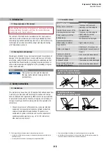
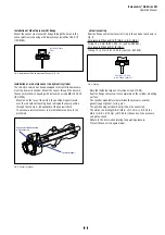
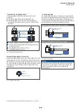
Fig. 12:
1RWLFHIRUWKUHDGHGĠDQJH0ūJEDVHGRQ',1,62
1RWHWKHIDVWHQLQJWRUTXHRI1P
6HDWWKHĠDQJHFRQWDFWVXUIDFHFRPSOHWHO\RQWKHF\OLQGHUPRXQWLQJ
surface.
The cylinder manufacturer determines the pressure-resistant
JDVNHWFRSSHUJDVNHW2ULQJHWF
The position magnet should not grind on the sensor rod.
7KHSLVWRQURGGULOOLQJŰPPŰLQGHSHQGVRQWKH
pressure and piston speed.
Adhere to the information relating to operating pressure.
Protect the sensor rod against wear.
1RWLFHIRUPHWULFWKUHDGHGĠDQJH
4.4 agnet instal lation
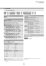
Typical use of magnets
agnet
%HQHğWV
Ring magnets
5RWDWLRQDOO\V\PPHWULFDOPDJQHWLFğHOG
-magnets
eight tolerances can be compensated
ounting ring magnets and -magnets
Install the magnet using non-magnetic material for mounting
device, screws, spacers etc.. The magnet must not grind on
the sensor rod. Alignment errors are compensated via the air gap.
3HUPLVVLEOHVXUIDFHSUHVVXUH0D[1PP
2
)DVWHQLQJWRUTXHIRU0VFUHZV1PXVHZDVKHULIQHFHVVDU\
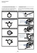
Minimum distance between position magnet and any magnetic
PDWHULDOKDVWREHPPLQ)LJ
If no other option exists and magnetic material is used, observe the
VSHFLğHGGLPHQVLRQV)LJ
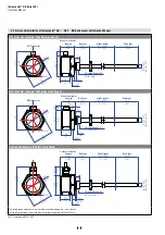
Fig. 13:
7\SLFDOXVHRIULQJPDJQHWVDQG8PDJQHWV
NOTICE
Mount ring magnets and U-magnets concentrically.
Do not exceed the maximum acceptable gap.
Fig. 14:
0RXQWLQJRI8PDJQHWSDUWQR
&RQWUROOLQJGHVLJQGLPHQVLRQVDUHLQPLOOLPHWHUVDQGPHDVXUHPHQWVLQDUHLQLQFKHV
Thread
d
d
2
d
3
d
4
d
5
.
.4
2
3
4
GB-
0ūJ Ű
Ű
24.5
2.4
2
26
Ź
Ød
5
Ra 3.2
Ra 3.2
Pitch diameter
A
A
Thread
(d
1
× P)
Ød
3
(Reference)
A
Ød
2
Ød
4
(Gauging)
This dimension applies when
tap drill cannot pass through
entire boss.
≤ R0.4
R0.3
R0.1
Z°
45
°
±
5
°
L
3
L
1
L
2
L
4
A
0.1
A
0.2
&RQWUROOLQJGHVLJQGLPHQVLRQVDUHLQPLOOLPHWHUV
M4
1
2
Air gap
Concentric mounting
of U-magnet
Part no. 201 553:
3 ±1 (0.12 ±0.04)
Part no. 251 416-2:
1.75 ±1 (0.07 ±0.04)
U-magnet
Non-magnetic mounting plate and fasteners
1
2


