9
Temposonics
®
GB-Series SSI
Operation Manual
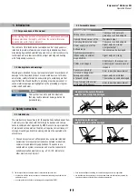
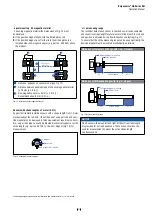
,QVWDOODWLRQRI*%ZLWKSUHVVXUHğWĠDQJH
0RXQWWKHVHQVRUYLDSUHVVXUHğWĠDQJHWKURXJKWKHERUHVLQWKH
VHQVRUHOHFWURQLFVKRXVLQJZLWKPDFKLQHVFUHZV0ū$
,62
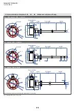
Fig. 4:
,QVWDOODWLRQRI*%ZLWKSUHVVXUHğWĠDQJHŊ6ʼn Ŋ1ʼn
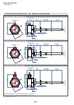
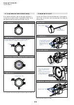
Fig. 5:
6HQVRULQF\OLQGHU
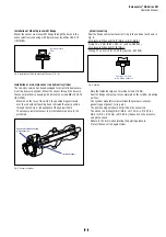
Installation of a rod-style sensor in a
hydraulic
cylinder
The rod-style version has been developed for direct stroke measure-
ment in a
hydraulic
cylinder. Mount the sensor through the bores in
WKHVHQVRUHOHFWURQLFVKRXVLQJZLWKPDFKLQHVFUHZV0ū$
,62
Mounted on the face of the piston, the position magnet travels
over the rod without touching it and indicates the exact position
WKURXJKWKHURGZDOOŋLQGHSHQGHQWRIWKHK\GUDXOLFĠXLG
The pressure resistant sensor rod is installed into a bore in the
piston rod.
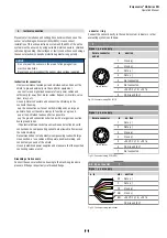
ydraulics sealing
6HDOWKHĠDQJHFRQWDFWVXUIDFHYLD2ULQJLQWKHXQGHUFXWDVVKRZQLQ
Fig. 6.
)RUSUHVVXUHğWĠDQJHI*%.*%1*%6
2ULQJūPP[LQSDUWQR
)RUSUHVVXUHğWĠDQJHI*%-
25LQJūPP[LQSDUWQR
Fig. 6: Sealing
1RWHWKHIDVWHQLQJWRUTXHRIPDFKLQHVFUHZVRI1P
6HDWWKHĠDQJHFRQWDFWVXUIDFHFRPSOHWHO\RQWKHF\OLQGHUPRXQWLQJ
surface.
The cylinder manufacturer determines the pressure-resistant
JDVNHWFRSSHUJDVNHW2ULQJHWF
The position magnet should not grind on the sensor rod.
7KHSLVWRQURGGULOOLQJ*%1*%6ŰPPŰLQ
*%-*%.ŰPPŰLQGHSHQGVRQWKHSUHVVXUH
and piston speed.
Adhere to the information relating to operating pressure.
Protect the sensor rod against wear.
Fastening torque
6 Nm
Sensor electronics housing
with sensor rod
Position magnet
Sealing via O-ring
in the flange undercut


