13
Temposonics
®
GB-Series SSI
Operation Manual
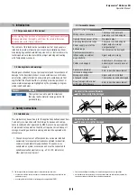
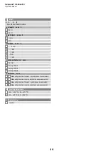
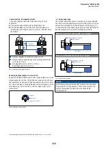
agnet mounting ith magnetic material
hen using magnetic material the dimensions of Fig. 15 must
be observed.
A.
If the position magnet aligns with the drilled piston rod
B.
If the position magnet is set further into the drilled piston rod,
LQVWDOODQRWKHUQRQPDJQHWLFVSDFHUHJSDUWQRDERYH
the magnet.
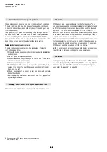
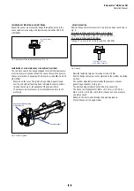
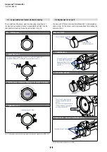
6HQVRUVZLWKVWURNHOHQJWKVŰPHWHUIW
6XSSRUWKRUL]RQWDOO\LQVWDOOHGVHQVRUVZLWKDVWURNHOHQJWKIURPPHWHU
mechanically at the rod end. ithout the use of a support, rod and posi -
tion magnet may be damaged. A false measurement result is also possi-
ble. onger rods require evenly distributed mechanical support over the
HQWLUHOHQJWKHJSDUWQR8VHDQ8PDJQHW)LJIRU
measurement.
Fig. 16:
([DPSOHRIVHQVRUVXSSRUW
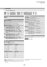
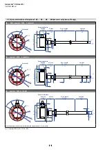
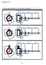
cti e measuring range
The technical data of each sensor is checked as well as documented
DQGWKHDFWLYHVWURNHOHQJWKXVHIXOHOHFWULFDOVWURNHZLWKLWVVWDUWDQG
HQGSRVLWLRQLVDGMXVWHGGXULQJğQDOLQVSHFWLRQDQGWHVWLQJ)LJ
To ensure that the entire measuring range can be used electrically, the
SRVLWLRQPDJQHWPXVWEHPRXQWHGPHFKDQLFDOO\DVIROORZV
*%6HULHVZLWKSUHVVXUHğWĠDQJHZLWKULQJ8PDJQHW
40
Stroke length
63.5
Reference edge of mounting
Start position
*%6HULHVZLWKWKUHDGHGĠDQJHZLWKULQJ8PDJQHW
40
Stroke length
63.5
Reference edge of mounting
Start position
)LJ$FWLYHPHDVXULQJUDQJH
NOTICE
On all sensors, the areas left and right of the active stroke length
DUHSURYLGHGIRUQXOODQGGHDG]RQH7KHVH]RQHVVKRXOGQRWEH
used for measurement, however the active stroke length
can be exceeded.
&RQWUROOLQJGHVLJQGLPHQVLRQVDUHLQPLOOLPHWHUVDQGPHDVXUHPHQWVLQDUHLQLQFKHV
Fig. 15:
,QVWDOODWLRQZLWKPDJQHWLFPDWHULDO
Magnet
Magnet
1
2
3
3
A
B
Magnetic
material
1XOO]RQHGHSHQGVRQVHQVRUPRGHOVHH)LJ
2
Distance between position magnet and any magnetic material
ŰPPŰLQ
3
1RQPDJQHWLFVSDFHUŰPPŰLQŋ
5HFRPPHQGDWLRQPPLQ
U-magnet
Sensor rod
Non-magnetic fixing clip


