


14
Temposonics
®
GB-Series SSI
Operation Manual
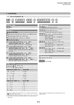
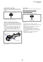
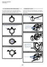
4.6 Replacement of ase unit
7KHEDVHXQLWRIWKHVHQVRUPRGHOV*%0DQG*%7LVUHSODFHDEOHDV
shown in Fig. 19. The sensor can be replaced without interrupting the
hydraulic circuit.
Base unit GB-B
Sensor electronics housing
Plastic tube with
inner sensor element
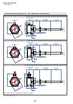
. oosen the scre s.
You do not need to loosen the screws
(3 screws DIN 915 M4x6 A2)
completely. Normally it is
sufficient if you turn the
screws 4 ×.
A/F 2
2. ull out the ase unit.
There is an O-ring inside the
flange of the GB-M and GB-T
sensor.
Position the O-ring as shown in
the figure before inserting the
new base unit (GB-B).
O-ring
3. Insert the ne ase unit. T ighten the scre s.
Fastening torque: 1.6 Nm
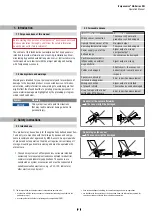
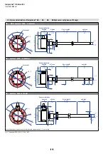
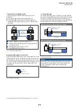
4.5 hange orientation of sensor electronics housing
The orientation of the sensor electronics housing respectively of
WKHHOHFWULFDOFRQQHFWLRQRIVHQVRUPRGHOV*%0DQG*%7FDQEH
FKDQJHGDIWHUPRXQWLQJ)ROORZWKHLQVWUXFWLRQVLQ)LJ
)LJ$OLJQVHQVRUHOHFWURQLFVKRXVLQJUHVSHFWLYHO\HOHFWULFDOFRQQHFWLRQRI*%0*%7
Fig. 19:
5HSODFHPHQWRIWKHEDVHXQLW*%%
GB- GB-T sensor
. oosen the scre s.
You do not need to loosen the screws (3 screws DIN 915 M4x6 A2)
completely. Normally it is sufficient if you turn the screws 3 ×.
A/F 2
2. Turn the sensor electronics housing to the desired orientation.
360°
3. Tighten the scre s.
Fastening torque: 1.6 Nm


