background image

56050801 - Rev B

10

© 2017 Telguard

If you cannot obtain a signal strength reading of 2 (TWO LEDS ON SOLID), you will
need to move the unit and/or remote the antenna higher, or switch to a special
antenna as described below.

Antenna Options

Antenna issues are unlikely unless the premises are located in a fringe network
coverage area, in a building below ground level, or in a metal structure. Telguard
offers a variety of high quality low-loss antenna cables as well as high gain
antennas listed in Appendix 6.

Step 3: Program, Activate & Transmit Alarms over Cellular Network

Confirm that the Telguard enables the alarm panel to transmit alarm events over the
cellular radio network.

The Telguard will confirm activation with the TCC if the

registration form was submitted prior to installation. Make sure that there is no
Telco connection for the panel to use, and trip a zone on the alarm panel. During
processing of the first alarm signal over the cellular network the Telguard will
transmit all programming parameters along with the information (central station
number and account code) from the alarm panel. Once this information is received,
the TCC will transmit a message back indicating that the unit is activated. Once
this message is received the LEDs on the unit will begin operating in normal mode;
Activation LED 1 will be on.

The initial alarm is to confirm registration and activate the Telguard. This alarm
will NOT be transmitted to the central station.

Special LED Indications during Activation

If the Telguard fails the activation process, it will be displayed on the LEDs.

If LED 1 and LED 4 are flashing, the Telguard has failed activation. The serial
number is not in the database at the TCC. Clear the fault (see note below) and
call Telguard Technical Support to verify proper registration before resending
an alarm signal.

If LEDs 1-5 are flashing, there is an activation error. The activation message
was NOT received at the TCC.

Clear the fault (see note below) and retry

transmitting an alarm signal.

If the Telguard fails a second time to activate,

check signal strength. If signal strength is OK, then call Telguard Technical
Support for further assistance.

NOTE: In order to clear the faults listed above, the RSSI button must be
pressed twice. After the issue has been resolved and the unit cleared, STEPS 3
AND 4 MUST BE REPEATED OR THE TELGUARD WILL NOT TRANSMIT ANY SIGNALS.

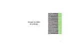
System Status LEDs Table

System Status LEDs

Activation Indications

LED 1-5 FLASHING

Failed Activation – Signal Too Weak

LED

1 & LED

4

FLASHING

Activation Error – Call Telguard Technical
Support

LED

1 ON

Activation Successful

System Trouble Condition, STC (LED 2) Table

Status LED

2

Indication

1 FLASH

ACFC - A/C Low or Missing

2 FLASH

LBC – Low Battery and/or Battery Charger
Failure

3 FLASH

LFC – Line Fault

Summary of Contents for TG-1 Express CDMA

Page 1: ...AL TG 1 RESIDENTIAL PRIMARY CELLULAR ALARM COMMUNICATOR INSTALLATION AND OPERATING INSTRUCTIONS COMPANY CONFIDENTIAL For use by TELGUARD customers only Distribution to other parties strictly prohibited August 17 2017 ...

Page 2: ...ble Monday Saturday 8am 8pm ET Toll Free 800 229 2326 option 9 About this Manual This manual assumes that you have basic security system installation skills such as measuring voltages stripping wire properly connecting wires together connecting wires to terminals and checking phone lines It also assumes that you have a familiarity with the proper installation and programming tasks related to vario...

Page 3: ...e power supply is off for any reason however briefly The cellular radio network needed to transmit alarm signals from protected premises to a central monitoring station may be inoperable or temporarily out of service Cellular radio networks are also subject to compromise by sophisticated methods of attack This equipment like any other electrical device is subject to component failure Although this...

Page 4: ...CT IN AN ENVIRONMENT NOT PROVIDED OR PERMITTED BY TELGUARD IN WRITING THE PARTIES SHALL GIVE EACH OTHER PROMPT NOTICE OF ANY SUCH COST OR CLAIMS AND COOPERATE EACH WITH THE OTHER TO EFFECTUATE THIS INDEMNIFICATION DEFENSE AND HOLD HARMLESS WARRANTY and LIMITATIONS TELGUARD WILL REPAIR OR REPLACE OUR OPTION INOPERATIVE UNITS FOR UP TO TWO YEARS FROM DATE OF MANUFACTURE EXCLUDES DAMAGE DUE TO LIGHTN...

Page 5: ...elays 4 Diagnostic and Status LEDs 4 Optional DC Operation 12VDC 5 Complete Factory Reset Option 5 UL and ULC Listings 5 Getting Ready 6 Dealer Account Establishment 6 Pre Installation Checklist 6 Installation 7 Summary 7 Step 1 Register the Telguard Unit 7 Step 2 Locate Unit and Measure Signal Strength RSSI 8 Step 3 Program Activate Transmit Alarms over Cellular Network 10 Step 4 Connect Supervis...

Page 6: ... Assignments 14 Compatible Alarm Panels 15 Appendix 2 Troubleshooting Guide 16 LED Indicator Guide Normal Operating Mode 16 LED Indicator Guide RSSI Mode 17 Troubleshooting Quick Reference Table 18 Appendix 3 Detailed Specifications 19 Dialer to Interface Electronics 19 Power 19 Digital Cellular Radio 19 Appendix 4 Accessories 20 ...

Page 7: ...elguard is installed in the same area as the Household alarm panel and is connected directly to the Household alarm panel via Telguard s RJ 45 jack Two programmable System Trouble Condition STC relays provide supervisory trip outputs for connection to the alarm panel s trip zone input terminals in order to provide a Telguard trouble signal to the alarm panel Additionally automatic self test and re...

Page 8: ...und 2300 Hz ack o 4 2 pulse 40pps Double Round 2300 Hz ack Contact ID Modem IIe IIIa2 4 SIA2 SIA DC 03 level 2 release at 300 baud DMP Hexadecimal account numbers can be used with 3 1 or 4 2 formats as well as Contact ID and Modem 4 or 10 digits for Contact ID 4 digits for Modem Complete Supervision of Communication Path The Telguard TG 1 continuously supervises the cellular communication path If ...

Page 9: ...12 1 volts the STC LED and STC relay restore The Telguard also indicates Low missing Battery Condition LBC when the battery charger fails AC Failure Condition ACFC AC failure condition ACFC is detected immediately when the AC power drops below 102 VAC When this condition is detected the STC LED blinks once the AC Power LED turns off and the STC trip output is activated after 2 hours When AC power ...

Page 10: ...ation The Remote Query is available via www telguard com The Remote Query causes the Telguard to upload current operational status data and historical data just as the automatic self test described above except that the query signal is controlled by the one who initiates it The query signal is held in the Telguard database at the TCC for review and is not forwarded on to the central station Progra...

Page 11: ...D will be OFF when operating in DC mode Battery will not charge on DC power Complete Factory Reset Option A special function within the Telguard allows you to perform a complete Factory Reset on the unit This reset will change all unit settings back to a factory default configuration Note Never attempt to do a Complete Factory Reset on an active account To begin the factory reset wait for the unit...

Page 12: ... Dealer Account has been established Pre Installation Checklist Before attempting to connect the Telguard to the alarm panel please make sure you have all the proper parts before you go to the job site The following items are shipped with each Telguard Telguard Cellular Communicator UL Listed plug in transformer Cellular Antenna Rechargeable 12V battery Pluggable screw terminal blocks 2 3 6 positi...

Page 13: ...our 24 7 dealer portal www telguard com The desired features and programmable options for any installation are selected during the registration process This includes STC strategy Trip Input enabling and added value services like HomeControl Flex Decide on a STC Trip Output Strategy The Telguard provides the host alarm panel with two supervisory trip outputs for reporting a Telguard system trouble ...

Page 14: ... determining the optimum cellular reception location Connect Power Option 1 Backup Battery and AC Power Transformer To apply power to the Telguard attach a battery to the battery connector jack using the supplied battery cable If the need for a different size cable arises the Telguard provides an alternate screw in terminal connection for the battery Backup battery must be sized appropriately to m...

Page 15: ...ption The higher the antenna the better Start in the drop ceiling above the unit and proceed from there up to the roof if necessary Remember the antenna should be as inconspicuous as possible for greatest visual security Try to keep the antenna away from sources of RF interference including pumps compressors ovens etc or where metal objects can shield it or otherwise block the cellular radio RF si...

Page 16: ...normal mode Activation LED 1 will be on The initial alarm is to confirm registration and activate the Telguard This alarm will NOT be transmitted to the central station Special LED Indications during Activation If the Telguard fails the activation process it will be displayed on the LEDs If LED 1 and LED 4 are flashing the Telguard has failed activation The serial number is not in the database at ...

Page 17: ...peration of Telguard Supervisory Output Check for proper operation of each programmed supervisory output by causing it to trip the alarm panel and making sure the proper LED illuminates and that the proper trouble code is reported to the central station Skip the testing of any supervisory functions that have not been enabled Note that the yellow LED 3 starts to flash when the alarm panel goes off ...

Page 18: ...n i e a cut wire can be detected When the trip input functionality is being used closing the trip contact will cause the Telguard to send a message to the TCC which in turn will cause the TCC to send a message to the central station If the Telguard is configured to report restorals the contact opening will also be reported Step 6 Complete the Telguard Installation The last step is to permanently m...

Page 19: ...H AC LOW MISSING 2 FLASH LBC LOW BATTERY 3 FLASH Not Used 4 FLASH NSC NO SERVICE 5 FLASH RFC RADIO FAILURE 6 FLASH DTF DIAL TONE FAIL 7 FLASH PPF PNL PRES FAIL LED 1 OFF NOT ACTIVATED ACTIVATED ON System Status LEDs Normal Mode ACTIVATION DENIED FLASHING ACTIVATION LED 2 OFF FLASHING SYSTEM TROUBLE NO TROUBLE TROUBLE LED 3 OFF PANEL COMM PANEL DIALER ON HOOK IDLE LED 4 OFF IDLE WAITING FOR RESPONS...

Page 20: ...pervisory Relay Trip output for programmable trouble conditions Normally Open 24 hour trip zone input on alarm panel Enables transmission of programmed supervisory trouble code see diagram or installation section STC LED 2 5 GND Trip Ground External trip relay Allows an external relay to trigger an alarm signal 6 IN Trip Input External trip relay Allows an external relay to trigger an alarm signal...

Page 21: ...ulse 10pps Double Round 1400 Hz ack o 3 1 pulse 20pps Double Round 2300 Hz ack o 3 1 pulse 40pps Double Round 2300 Hz ack o 4 2 pulse 20pps Double Round 1400 Hz ack o 4 2 pulse 20pps Double Round 2300 Hz ack o 4 2 pulse 40pps Double Round 2300 Hz ack Contact ID Modem IIe IIIa2 4 SIA2 SIA DC 03 level 2 release at 300 baud DMP The installer should verify compatibility at the time of installation ...

Page 22: ...m Trouble Condition NSC 5 Flashes System Trouble Condition RFC 6 Flashes System Trouble Condition DTF 7 Flashes System Trouble Condition PPF LED 3 MODE Yellow Off Alarm panel idle Telguard is primary or Sole Path Flash 1 sec Alarm panel off hook to transmit signals over cellular On Unused LED 4 Acknowledgeme nt Red Solid On The Telguard is waiting for acknowledgement from the TCC Off Idle state Fl...

Page 23: ...m NO SVC LED 5 slow flash LED 4 2 off n a 1 LED 5 on LED 4 2 off 111 1 LED 5 on LED 4 slow flash LED 3 2 off 110 2 LED 5 4 on LED 3 2 off 100 Minimum acceptable signal strength 2 LED 5 4 on LED 3 slow flash LED 2 off 90 3 LED 5 3 on LED 2 off 80 3 LED 5 3 on LED 2 slow flash 70 4 LED 5 2 on 60 ...

Page 24: ...Activation LED 1 off Yes None The Telguard will not function until the first signal is sent through the Telguard to activate the unit Automatic Self Test Radio LED 5 flashes during transmit None Yes Self test Send Self test information to central station via TCC return to ready state Telguard Remote Query Communication Center Activated by Customer Service Radio LED 5 flashes during transmit None Y...

Page 25: ...nic short circuit protection Maximum charging current of 240mA Transformer Supplied 12 VAC 10VA UL plug in acceptable transformers GlobTek part number WA1E800J00 N GTGTAB Tri Mag part number WTD 1208 C Average DC Current Draw 6 2VDC 64mA idle 265mA transmitting 12VDC 34mA idle 121mA transmitting 16VDC 28mA idle 117mA transmitting Digital Cellular Radio The Telguard cellular radio provides data con...

Page 26: ... 35 35 feet of low loss high performance antenna cable and mounting bracket ACD 50 50 feet of low loss high performance antenna cable and mounting bracket ACD 100 100 feet of low loss high performance antenna cable and mounting bracket HGDL 0 High Gain Directional Antenna EXDL 0 External Omni Directional Antenna ...

Reviews: