


5 – Operating Software
DPN 402196 Issue 4.1
© Teledyne TSS
5- 19
❐
Red indicates an uncleared error.
❐
Yellow indicates an event.
❐
Green indicates an information message.
The System Errors window includes a status line that has two data fields. These show the total number
of cleared and uncleared errors since you started DeepView for Windows.
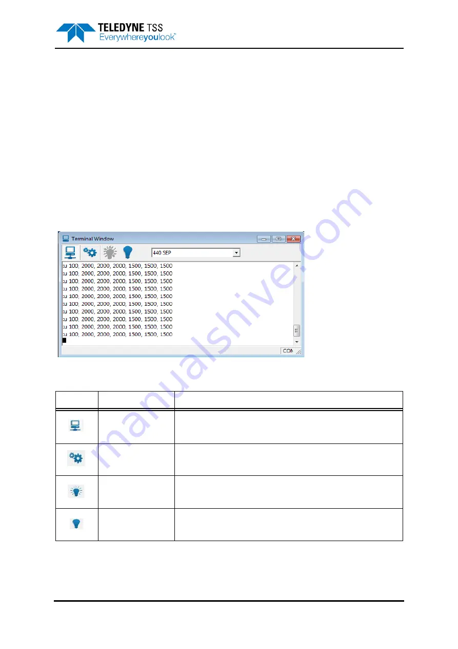
5.3.2.6 Terminal Window
The Terminal Window, shown in
, allows you to send and view data to and from the SEP and
the altimeter. It has a toolbar, a client area that displays black text against a white background, and a
status bar.
The figure shows the Terminal Window displaying data packets from the 440 SEP in the client area. If
you select the altimeter as the active serial device, the client area will show data packets from this
device instead.
Figure 5-8: Terminal window
There is also a drop-down box that allows you to select the active serial device from among those
available. This box includes the option to use the Terminal Window as a ‘dumb terminal’ if necessary
(also accessible by pressing [ALT][Down arrow] then release [ALT]).
Table 5-3: Terminal Window toolbar
Button
Function
Explanation
Enable/Disable SEP
polling
This button has a toggle action that pauses and resumes SEP polling with
alternate presses. With this button deselected, DeepView does not send the
necessary characters that request data packets from the SEP.
Terminal properties
[ALT][T]
Use this button to set the serial communication parameters for the active
serial device.
Connect
This button allows you to connect the terminal to the active serial device.
Hang Up
This button allows you to disconnect the terminal from the active serial
device.
Summary of Contents for 440
Page 12: ...List of Figures x Teledyne TSS DPN 402196 Issue 4 1 ...
Page 18: ...Glossary xvi Teledyne TSS DPN 402196 Issue 4 1 ...
Page 24: ...1 Introduction 1 6 Teledyne TSS DPN 402196 Issue 4 1 ...
Page 32: ...2 System Overview 2 8 Teledyne TSS DPN 402196 Issue 4 1 ...
Page 66: ...4 Electrical Installation 4 20 Teledyne TSS DPN 402196 Issue 4 1 ...
Page 88: ...5 Operating Software 5 22 Teledyne TSS DPN 402196 Issue 4 1 Figure 5 10 Altimeter Test ...
Page 144: ...6 Operating Procedure 6 40 Teledyne TSS DPN 402196 Issue 4 1 ...
Page 154: ...7 Operational Considerations 7 10 Teledyne TSS DPN 402196 Issue 4 1 ...
Page 164: ...8 System Specifications 8 10 Teledyne TSS DPN 402196 Issue 4 1 ...
Page 203: ...10 System Drawings DPN 402196 Issue 4 1 Teledyne TSS 10 17 Figure 10 15 SDC10 Dimensions ...
Page 230: ...A Operating Theory A 12 Teledyne TSS DPN 402196 Issue 4 1 ...
Page 242: ...B Options B 12 Teledyne TSS DPN 402196 Issue 4 1 ...
Page 244: ...C Altimeter C 2 Teledyne TSS DPN 402196 Issue 4 1 ...
Page 246: ...D Reference D 2 Teledyne TSS DPN 402196 Issue 4 1 ...
Page 248: ...D Reference D 4 Teledyne TSS DPN 402196 Issue 4 1 ...
Page 250: ...D Reference D 6 Teledyne TSS DPN 402196 Issue 4 1 ...
Page 252: ...D Reference D 8 Teledyne TSS DPN 402196 Issue 4 1 ...
Page 254: ...D Reference D 10 Teledyne TSS DPN 402196 Issue 4 1 ...