


A – Operating Theory
A-10
© Teledyne TSS
DPN 402196 Issue 4.1
A.2.5 Trenching Vehicles
In the case of a crawling ROV, it may not be possible to lift the vehicle off the seabed. However, very
good survey information can still be obtained merely by selecting the correct water temperature.
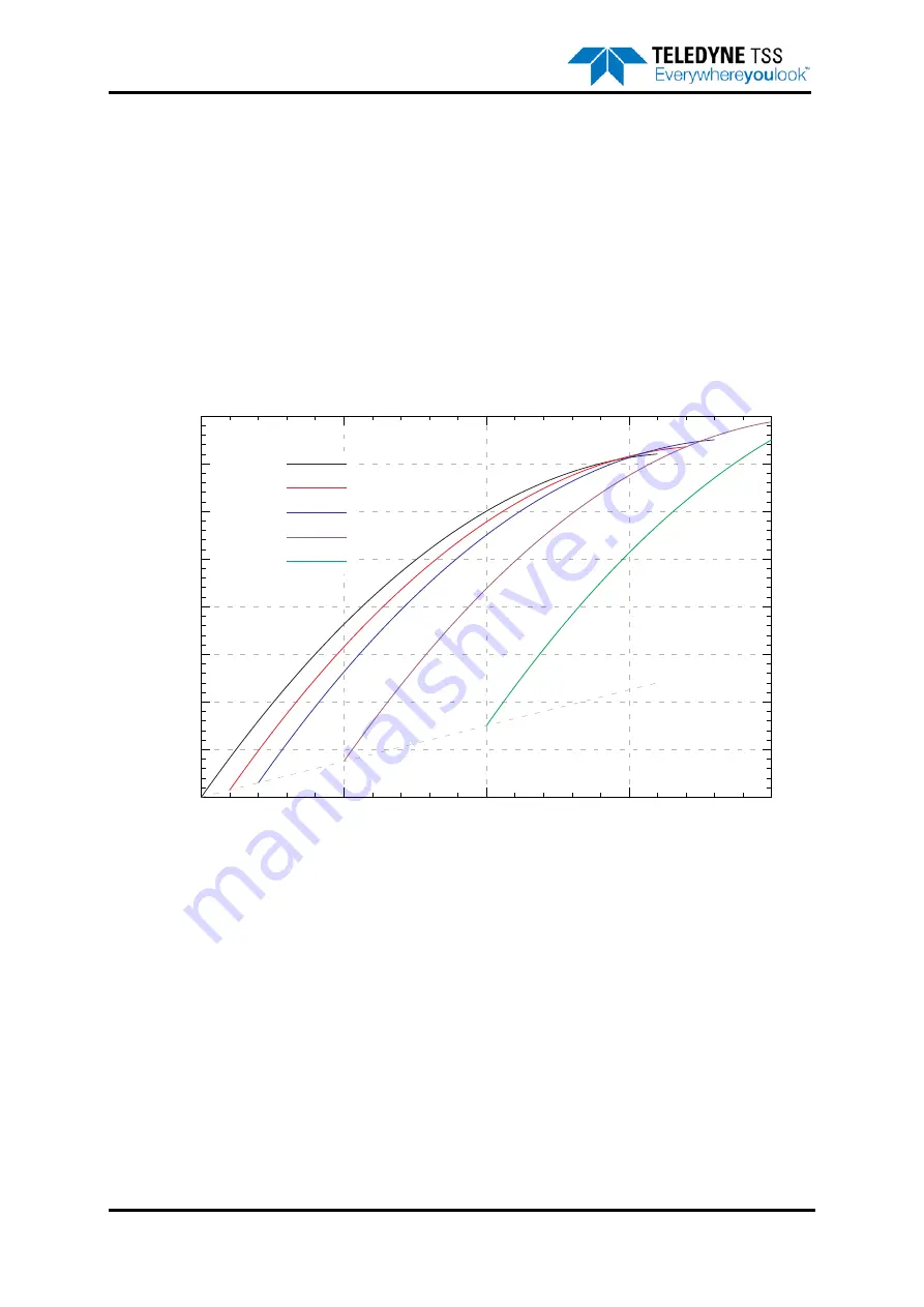
A.2.6 Limitations
shows typical lift curves with a fixed target is present. Although this situation does not
appear when surveying, it shows how the software has to separate the seawater and target
components of the returned voltages. The solid curve (“No target”) shows a seawater lift curve with
only seawater present. If a 10µV target signal is present, then this curve will be repeated, but shifted
10µV to the right, and 30µV upwards. At an early voltage of approximately 140µV, this curve crosses
the “No target” curve.
Figure A-10: Typical lift curves with a fixed target present
This means that if the seawater rejection mechanism is faced with early and standard voltages of 140
and 1450µV, it will be unable to decide if a target is present or not. This means that at 140µV of
seawater, the algorithm will not work correctly and return a less accurate value for range. However, this
point occurs only when the ROV is approximately 4m above the seabed, well beyond the range of a
typical survey.
In more conductive water, the seawater parameters change, and the crossing point moves to perhaps
250µV. The increase in seawater signal means that the point where the algorithm begins to break
down remains at roughly 4m.
A sudden jump in the target voltages when the ROV is lifted is to be expected, and is not due to a
deficiency in the system or its configuration.
0
200
400
600
800
1000
1200
1400
1600
0
50
100
150
200
Early
V
oltage
Standard Voltage
Lift curves with fixed target present
m=17, g=-0.05
No target
10uV
20uV
50uV
100uV
Summary of Contents for 440
Page 12: ...List of Figures x Teledyne TSS DPN 402196 Issue 4 1 ...
Page 18: ...Glossary xvi Teledyne TSS DPN 402196 Issue 4 1 ...
Page 24: ...1 Introduction 1 6 Teledyne TSS DPN 402196 Issue 4 1 ...
Page 32: ...2 System Overview 2 8 Teledyne TSS DPN 402196 Issue 4 1 ...
Page 66: ...4 Electrical Installation 4 20 Teledyne TSS DPN 402196 Issue 4 1 ...
Page 88: ...5 Operating Software 5 22 Teledyne TSS DPN 402196 Issue 4 1 Figure 5 10 Altimeter Test ...
Page 144: ...6 Operating Procedure 6 40 Teledyne TSS DPN 402196 Issue 4 1 ...
Page 154: ...7 Operational Considerations 7 10 Teledyne TSS DPN 402196 Issue 4 1 ...
Page 164: ...8 System Specifications 8 10 Teledyne TSS DPN 402196 Issue 4 1 ...
Page 203: ...10 System Drawings DPN 402196 Issue 4 1 Teledyne TSS 10 17 Figure 10 15 SDC10 Dimensions ...
Page 230: ...A Operating Theory A 12 Teledyne TSS DPN 402196 Issue 4 1 ...
Page 242: ...B Options B 12 Teledyne TSS DPN 402196 Issue 4 1 ...
Page 244: ...C Altimeter C 2 Teledyne TSS DPN 402196 Issue 4 1 ...
Page 246: ...D Reference D 2 Teledyne TSS DPN 402196 Issue 4 1 ...
Page 248: ...D Reference D 4 Teledyne TSS DPN 402196 Issue 4 1 ...
Page 250: ...D Reference D 6 Teledyne TSS DPN 402196 Issue 4 1 ...
Page 252: ...D Reference D 8 Teledyne TSS DPN 402196 Issue 4 1 ...
Page 254: ...D Reference D 10 Teledyne TSS DPN 402196 Issue 4 1 ...